Reelmaster 5500-D
Page 8 - 16
Cutting Units
Daily Adjustments
Prior to each day’s mowing, or as required, each cutting
unit must be checked to verify proper bedknife−to−reel
contact. This must be performed even though quali-
ty of cut is acceptable.
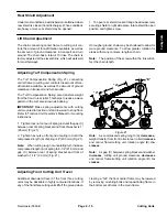
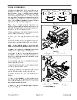
1. Lower cutting units onto a hard surface, shut off en-
gine and remove key from ignition.
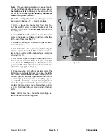
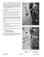
2. Slowly rotate reel in reverse direction listening for
reel−to−bedknife contact. If no contact is evident, turn
bedknife adjusting knob clockwise, one click at a time,
until light contact is felt and heard.
3. If excessive contact is felt, turn bedknife adjusting
knob counterclockwise, one click at a time until no con-
tact is evident. Then turn bedknife adjusting knob one
click at a time clockwise, until light contact is felt and
heard.
IMPORTANT: Light contact is preferred at all times. If
light contact is not maintained, bedknife / reel edges will
not sufficiently self−sharpen and dull cutting edges will
result after a period of operation. If excessive contact is
maintained, bedknife/reel wear will be accelerated, un-
even wear can result, and quality of cut may be adverse-
ly affected.
Note:
As the reel blades continue to run against the
bedknife a slight burr will appear on the front cutting
edge surface the full length of the bedknife. If a file (or
a light face grind) is occasionally run across the front
edge to remove this burr, improved cutting edge sharp-
ness can be obtained.
After extended running, a ridge will eventually develop
at both ends of the bedknife. These notches must be
rounded off or filed flush with cutting edge of bedknife to
assure smooth operation.
Service and Repairs
Backlapping
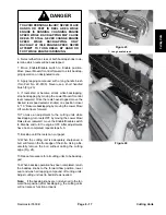
DANGER
REELS MAY STALL WHILE BACKLAPPING.
DO NOT ATTEMPT TO RESTART REELS BY
HAND OR TOUCH REELS WHILE
BACKLAPPING. STOP ENGINE AND TURN
H.O.C. KNOB ONE POSITION TOWARD ”1”.
Note:
When backlapping, the front units all operate to-
gether, and the rear units operate together.
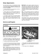
1. Position the machine on a level surface, lower the
cutting units, stop the engine, engage the parking brake,
and move the Enable/Disable switch to disable position.
2. Unlock and raise the seat to expose controls.
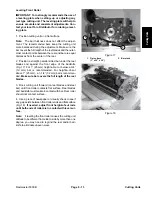
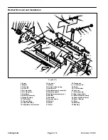
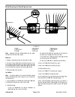
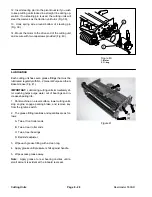
3. Locate the reel speed selector knobs and backlap
knobs (Fig. 22). Rotate the desired backlap knob(s) to
the backlap position and the desired reel speed selector
knob(s) to position “1.”
Note:
Backlapping speed may be increased by mov-
ing the reel speed selector knob toward “13.” Each posi-
tion will increase speed approximately 100 rpm. After
changing selector, wait 30 seconds for the system to sta-
bilize at the new speed.
Figure 22
1. Reel speed selector knobs
2. Backlap knobs
1
1
2
2
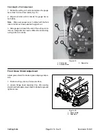
4. Make initial reel to bedknife adjustments appropriate
for backlapping on all cutting units which are to be back-
lapped.
5. Start engine and run at idle speed.
Summary of Contents for 00075SL
Page 2: ...Reelmaster 5500 D ...
Page 4: ...Reelmaster 5500 D ...
Page 6: ...Reelmaster 5500 D ...
Page 64: ...Reelmaster 5500 D Hydraulic System Rev C Page 4 26 This page is intentionally blank ...
Page 170: ...Reelmaster 5500 D Page 5 40 Electrical System Rev C ...
Page 192: ...Reelmaster 5500 D Differential Axle Page 6 22 ...
Page 254: ...Reelmaster 5500 D Groomer Rev C Page 8 1 14 ...
Page 278: ...Reelmaster 5500 D Page 10 2 Electrical Diagrams Rev C ...
Page 284: ...Rev C Page 10 8 Harness Drawing Reelmaster 5500 D Serial Number 210000401 to 210999999 ...
Page 285: ...Rev C Page 10 9 Harness Diagram Reelmaster 5500 D Serial Number 210000401 to 210999999 ...
Page 286: ...Rev C Page 10 10 Harness Drawing Reelmaster 5500 D Serial Number 220000001 to 220999999 ...
Page 287: ...Rev C Page 10 11 Harness Diagram Reelmaster 5500 D Serial Number 220000001 to 220999999 ...
Page 288: ...Rev C Page 10 12 Harness Drawing Reelmaster 5500 D Serial Number Above 230000000 ...
Page 289: ...Rev C Page 10 13 Harness Diagram Reelmaster 5500 D Serial Number Above 230000000 ...
Page 290: ...Reelmaster 5500 D ...

