Reelmaster 5500-D
Hydraulic System (Rev. C)
Page 4 - 68
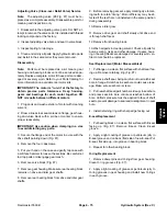
Filter By-Pass Valve Replacement
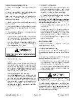
1. Park machine on a level surface, lower cutting units,
stop engine, engage parking brake, and remove key
from the ignition switch.
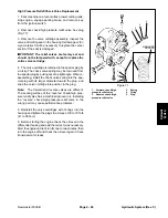
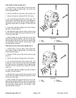
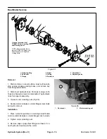
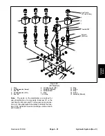
2. Remove the filter by−pass valve hex plug (Fig. 80).
3. Remove the spring and poppet from the housing.
4. Do not interchange parts with another valve. The
spring used in the filter by−pass valve is identified by a
red dye mark, and requires a force of approximately 2.2
lb (9.8 N) to compress it to a length of 1.280 inch (3.25
cm).
5. Inspect the poppet and mating seat in the end cap for
damage or foreign material.
6. Reinstall the poppet, spring and plug (with O-ring)
into the housing. Tighten the plug to a torque from 30 to
70 ft.-lb (41 to 95 N-m).
7. Before starting the engine check the oil level in the
differential housing and add the correct oil as necessary.
Start the engine and let it run for one to two minutes, then
turn the engine off and check the oil level again. Check
the transmission for leaks.
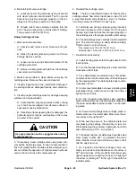
Filter Reverse Flow Check Valve Replacement
1. Park machine on a level surface, lower cutting units,
stop engine, engage parking brake, and remove key
from the ignition switch.
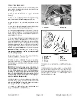
2. Remove the filter reverse flow check valve hex plug
(Fig. 81).
3. Remove the spring and poppet from the housing.
4. Do not interchange parts with another valve. The
spring used in the reverse flow check valve is identified
by a blue dye mark, and requires a force of approximate-
ly 0.3 lb (1.3 N) to compress it to a length of 1.280 inch
(3.25 cm).
5. Inspect the poppet and mating seat in the end cap for
damage or foreign material.
6. Reinstall the poppet, spring and plug (with O-ring)
into the housing. Tighten the plug to a torque from 30 to
70 ft.-lb (41 to 95 N-m).
7. Before starting the engine check the oil level in the
differential housing and add the correct oil as necessary.
Start the engine and let it run for one to two minutes, then
turn the engine off and check the oil level again. Check
the transmission for leaks.
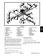
1. Plug
2. O-ring
3. Spring
4. Relief
valve
Figure 80
1
2
3
4
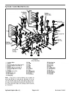
1. Plug
2. O-ring
3. Spring
4. Relief
valve
Figure 81
1
2
3
4
Summary of Contents for 00075SL
Page 2: ...Reelmaster 5500 D ...
Page 4: ...Reelmaster 5500 D ...
Page 6: ...Reelmaster 5500 D ...
Page 64: ...Reelmaster 5500 D Hydraulic System Rev C Page 4 26 This page is intentionally blank ...
Page 170: ...Reelmaster 5500 D Page 5 40 Electrical System Rev C ...
Page 192: ...Reelmaster 5500 D Differential Axle Page 6 22 ...
Page 254: ...Reelmaster 5500 D Groomer Rev C Page 8 1 14 ...
Page 278: ...Reelmaster 5500 D Page 10 2 Electrical Diagrams Rev C ...
Page 284: ...Rev C Page 10 8 Harness Drawing Reelmaster 5500 D Serial Number 210000401 to 210999999 ...
Page 285: ...Rev C Page 10 9 Harness Diagram Reelmaster 5500 D Serial Number 210000401 to 210999999 ...
Page 286: ...Rev C Page 10 10 Harness Drawing Reelmaster 5500 D Serial Number 220000001 to 220999999 ...
Page 287: ...Rev C Page 10 11 Harness Diagram Reelmaster 5500 D Serial Number 220000001 to 220999999 ...
Page 288: ...Rev C Page 10 12 Harness Drawing Reelmaster 5500 D Serial Number Above 230000000 ...
Page 289: ...Rev C Page 10 13 Harness Diagram Reelmaster 5500 D Serial Number Above 230000000 ...
Page 290: ...Reelmaster 5500 D ...

