Reelmaster 5500-D
Page 5 - 12
Electrical System (Rev. C)
If 4 beeps are heard:
The most common cause for a 4 beep signal is from an
improper oil level reading. Make sure machine is on a
level surface when checking oil level. Since oil level will
vary with temperature, it is best to check when cool.
1.
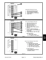
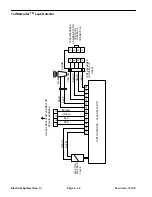
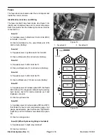
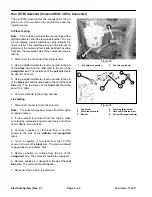
When toggling “input”, a LED should display (Fig. 9)
any of the following problems diagnosed by the TurfDe-
fender:
Oil level low: Position machine on a level surface
and fill to proper level.
Oil level high: Position machine on a level surface
and remove excess oil until proper level is attained.
Oil too hot: Allow machine to cool and clean any de-
bris from oil cooler.
Air leak in system: Assure tank cap is tight or check
for leak in tank.
Note: Only large air leaks can be detected by Turf-
Defender.
2.
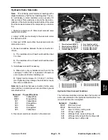
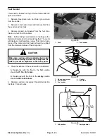
When toggling “output” a LED should display
(Fig. 10) any of the following problems diagnosed by the
TurfDefender:
Valve open circuit (LED blinking): Check / replace
TurfDefender electric solenoid valve or wires.
Valve short circuit (LED blinking): Check / replace
TurfDefender electric solenoid valve or wires.
Self diagnostic LED Blinking: Internal circuit failure
in TurfDefender.
Data Line LED Blinking: Problem with communica-
tions between machine and leak detector; or prob-
lem with wires.
Note: If machine must be operated with leak detec-
tor disabled, unplug leak detector 4-pin connector
from 4-pin connector of main harness. Do not un-
plug leak detector alarm.
If false alarms are observed:
1.
Oil level may be low causing air to be drawn into the
system. Check oil level.
2.
Extremely hard left turns can cause oil to slosh to
the right, exposing suction line and purging air out of
system. Normal maneuvering should not cause this
condition.
3.
Air leak in system. Check to make sure cap is se-
curely on tank.
Note: The system will reset itself whenever the igni-
tion key is turned to “OFF” position. The hand held Diag-
nostic ACE must be connected and observed during a
false alarm. Once the ignition key is turned to “OFF”
position, the TurfDefender will reset itself.
4.
To check for a system problem, install hand held
Diagnostic ACE, toggle input/output and check for any
problems previously discussed.
5.
Your Authorized Toro Distributor has equipment to
analyze system problems.
IMPORTANT: The Diagnostic ACE displays must not
be left connected to the machine. It is not designed
to withstand the environment of the machine’s ev-
ery day use. When done using Diagnostic ACE, dis-
connect them from the machine and reconnect
loopback connectors to harness connectors. Ma-
chine will not operate without loopback connectors
installed on harness. Store Diagnostic ACE in dry,
secure location in shop, not on machine.
Summary of Contents for 00075SL
Page 2: ...Reelmaster 5500 D ...
Page 4: ...Reelmaster 5500 D ...
Page 6: ...Reelmaster 5500 D ...
Page 64: ...Reelmaster 5500 D Hydraulic System Rev C Page 4 26 This page is intentionally blank ...
Page 170: ...Reelmaster 5500 D Page 5 40 Electrical System Rev C ...
Page 192: ...Reelmaster 5500 D Differential Axle Page 6 22 ...
Page 254: ...Reelmaster 5500 D Groomer Rev C Page 8 1 14 ...
Page 278: ...Reelmaster 5500 D Page 10 2 Electrical Diagrams Rev C ...
Page 284: ...Rev C Page 10 8 Harness Drawing Reelmaster 5500 D Serial Number 210000401 to 210999999 ...
Page 285: ...Rev C Page 10 9 Harness Diagram Reelmaster 5500 D Serial Number 210000401 to 210999999 ...
Page 286: ...Rev C Page 10 10 Harness Drawing Reelmaster 5500 D Serial Number 220000001 to 220999999 ...
Page 287: ...Rev C Page 10 11 Harness Diagram Reelmaster 5500 D Serial Number 220000001 to 220999999 ...
Page 288: ...Rev C Page 10 12 Harness Drawing Reelmaster 5500 D Serial Number Above 230000000 ...
Page 289: ...Rev C Page 10 13 Harness Diagram Reelmaster 5500 D Serial Number Above 230000000 ...
Page 290: ...Reelmaster 5500 D ...

