Steering
and Brakes
Reelmaster 5500-D
Steering and Brakes
Page 7 - 15
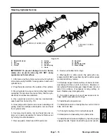
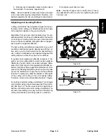
Steering Cylinder Service
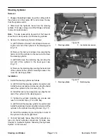
1. Barrel with clevis
2. Nut
3. Uni-ring
4. Piston
5. O-ring
6. Rod
seal
7. O-ring
8. Back-up
ring
9. Head
10. Dust seal
11. Collar
12. Shaft with clevis
13. Grease fitting
Figure 18
STEERING CYLINDER (2WD)
STEERING CYLINDER
(4WD)
10
7
3
5
8
6
11
12
1
2
4
9
10
7
3
5
6
12
1
13
2
4
9
7
13
IMPORTANT: To prevent damage to rod or barrel,
clamp vise on pivot ends only. DO NOT clamp
against smooth rod surface.
1. After removing the cylinder, pump oil out of cylinder
into a drain pan by SLOWLY moving piston in and out of
cylinder bore.
2. Plug the ports and clean the outside of the cylinder.
3. Mount cylinder in a vise so rod end of cylinder is tilted
up slightly. Do not close the vise so firmly that the cylin-
der barrel could become distorted.
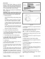
4. Use a spanner wrench to unscrew (counterclock-
wise) head from barrel (Fig. 18).
5. Grasp large end of piston rod and use a twisting and
pulling motion to carefully extract piston, rod, and head
from cylinder tube.
6. Securely mount piston, rod, and head into vise so
large nut is easily accessible for removal. Remove nut
by turning it counterclockwise.
7. Remove piston. Slide head off of piston rod.
8. Remove all seals and O−rings.
9. Wash parts in a safe solvent. Dry parts with com-
pressed air. DO NOT wipe them dry with a cloth or paper
as lint and dirt may remain.
10.Carefully inspect internal surface of barrel for dam-
age (deep scratches, out−of−round, etc.). Replace en-
tire cylinder if barrel is damaged. Inspect head, rod, and
piston for evidence of excessive scoring, pitting, or
wear. Replace any damaged parts.
11. Put a light coating of oil on all new seals, and O−
rings. Install new seals and O−rings.
12.Install head onto piston rod.
13.Install piston onto rod and tighten hex nut to 30 to 34
ft-lbs. (40 to 46 Nm).
14.Put a light coating of oil on all cylinder parts.
15.Slide piston rod assembly into cylinder tube.
16.Install head into tube and tighten by hand to properly
engage threads. Tighten head with a spanner wrench.
Summary of Contents for 00075SL
Page 2: ...Reelmaster 5500 D ...
Page 4: ...Reelmaster 5500 D ...
Page 6: ...Reelmaster 5500 D ...
Page 64: ...Reelmaster 5500 D Hydraulic System Rev C Page 4 26 This page is intentionally blank ...
Page 170: ...Reelmaster 5500 D Page 5 40 Electrical System Rev C ...
Page 192: ...Reelmaster 5500 D Differential Axle Page 6 22 ...
Page 254: ...Reelmaster 5500 D Groomer Rev C Page 8 1 14 ...
Page 278: ...Reelmaster 5500 D Page 10 2 Electrical Diagrams Rev C ...
Page 284: ...Rev C Page 10 8 Harness Drawing Reelmaster 5500 D Serial Number 210000401 to 210999999 ...
Page 285: ...Rev C Page 10 9 Harness Diagram Reelmaster 5500 D Serial Number 210000401 to 210999999 ...
Page 286: ...Rev C Page 10 10 Harness Drawing Reelmaster 5500 D Serial Number 220000001 to 220999999 ...
Page 287: ...Rev C Page 10 11 Harness Diagram Reelmaster 5500 D Serial Number 220000001 to 220999999 ...
Page 288: ...Rev C Page 10 12 Harness Drawing Reelmaster 5500 D Serial Number Above 230000000 ...
Page 289: ...Rev C Page 10 13 Harness Diagram Reelmaster 5500 D Serial Number Above 230000000 ...
Page 290: ...Reelmaster 5500 D ...

