background image


iSort

 Automated Cell Sorter User Guide


27 


4.


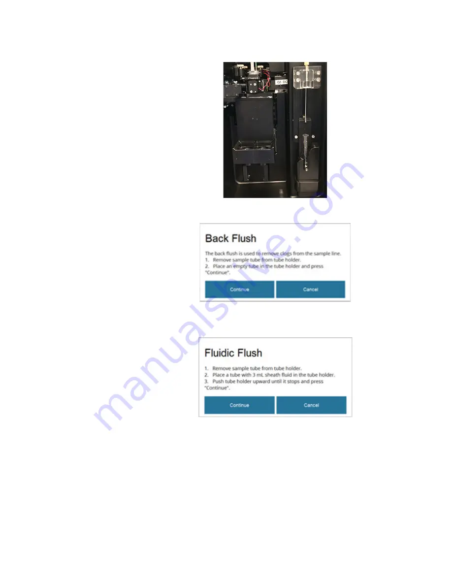
When prompted, place an empty 12 × 75-mm sample tube into the sample tube 
holder in the down position.  


5.


Press 

Continue

 to begin the back flush component of the initial cleaning cycle, 

which removes clogs from the sample lines. 


6.


When prompted, place a fresh 12 × 75-mm sample tube with 3 mL of sheath 

fluid into the sample tube holder, then move the sample tube holder to the up 
position.  


7.


Press 

Continue

 to begin the fluidic flush component of the initial cleaning 

cycle, which washes the sample lines with sheath fluid and is designed to 
prevent carryover between samples. 

8.


At the completion of the initial cleaning, a prompt will confirm “Initial 
Cleaning Complete”. Proceed to Performance Test (page 28) or Analyze and 

Sort (page 31). 


Summary of Contents for invitrogen iSort Series

Page 1: ...For Research Use Only Not for use in diagnostic procedures iSort Automated Cell Sorter Catalog Number A33041 Publication Number MAN0016718 Revision A 0...

Page 2: ...October 2018 New user guide Important Licensing Information These products may be covered by one or more Limited Use Label Licenses By use of these products you accept the terms and conditions of all...

Page 3: ...ation workflow 15 Site preparation checklist 15 Pre installation requirements 16 Operating environment and site requirements 17 Safety requirements 18 Materials required for installation 19 Prepare fo...

Page 4: ...e 82 System Update 84 View Log 86 Remote Service 87 7 Shut Down 88 Daily Shut Down 88 8 Settings 92 9 Instrument care and maintenance 94 Planned maintenance schedule 94 General care 96 Cleaning proced...

Page 5: ...on instruments 130 Safety labels on instruments 132 General instrument safety 133 Chemical safety 134 Chemical waste safety 135 Electrical safety 136 Physical hazard safety 137 Biological hazard safet...

Page 6: ...accurate installation or safe use of a chemical Safety alert words Three safety alert words appear in this document at points where you need to be aware of relevant hazards Each alert word CAUTION WAR...

Page 7: ...ent and consistent workflow The small footprint allows the self contained iSort Automated Cell Sorter to fit within a standard biosafety cabinet or on a basic laboratory cart for portability Product u...

Page 8: ...paration Sysmex 04 0042 2317 PBS 1X pH 7 4 flow cytometry grade Sheath fluid sample preparation Thermo Fisher Scientific A1286301 PBS 10X pH 7 4 Calibration and QC Thermo Fisher Scientific 70011044 Tw...

Page 9: ...rument exterior components Front view Touch screen monitor Sorting compartment Power button Fluidics compartment USB port Type A Sample pump compartment Front view with sorting compartment door open F...

Page 10: ...MPORTANT The HDMI port is used by Technical Service representatives to monitor system performance with diagnostic tools We do not recommend attaching an external monitor to the iSort Automated Cell So...

Page 11: ...tion of 1 5 mL 5 mL or 50 mL tubes Collection tubes 5 mL tubes shown Sort chamber door shown open Sample tube holder shown in down position Sample tube 12 75 mm tube with 5 mL sample capacity Sample i...

Page 12: ...Sample pump compartment Note The front of the instrument is facing to the left Top cover Sample pump dampener Sorting compartment door Sample pump Sample line Rear view of instrument with the top cove...

Page 13: ...tains fluidics lines filters and the sheath pump Sheath fluid container Sheath fluid lines clear Fluid containers detail Waste container 2 L capacity Sheath fluid container 2 L capacity Waste fluid li...

Page 14: ...nt is designed for quick verification of sample content and can be performed independently of the Sort workflow For a detailed description of the Analyze workflow see page 31 Files Allows you to manag...

Page 15: ...maintenance functions Additional training is provided separately by a Thermo Fisher Scientific Applications specialist Site preparation checklist IMPORTANT Complete all items in the checklist before t...

Page 16: ...o the site before the installation date Available to help service representative and laboratory personnel throughout installation Review safety information Ensure that all customer provided materials...

Page 17: ...e iSort Automated Cell Sorter should be placed on a level surface away from vibrations from other pieces of equipment Tabletop centrifuges vortex mixers and other laboratory equipment can vibrate the...

Page 18: ...fires as specified in current codes regulations and or standards and with approval of the Fire Marshall or other authority having jurisdiction Eyewash Safety shower Eye and hand protection Sufficient...

Page 19: ...and inspect the shipment Carefully inspect the shipping containers and report any damage to the Thermo Fisher Scientific service representative Record any damage or mishandling on the shipping docume...

Page 20: ...on the weight moving or lifting an instrument may require two or more persons IMPORTANT Do not lift the iSort Automated Cell Sorter from the fluidics compartment Lifting from the fluidics compartment...

Page 21: ...he Attune Performance Tracking Beads for use in the daily performance test page 28 Deionized water Used in various cleaning and maintenance procedures for overnight storage of the instrument when not...

Page 22: ...or the other deflection plate Deflection plates removed Deflection plates reinstalled IMPORTANT The deflection plates must be removed and cleaned on a regular basis to prevent any buildup of deposit p...

Page 23: ...the fluid containers Visually inspect the sample input port fluidics tanks and connections and the pumps for any leakage If you notice any leaks in the fluidics lines contact your service representati...

Page 24: ...whenever you refill the sheath fluid to prevent the overfilling of the waste container during a run 6 Add 200 mL of full strength bleach solution into the emptied waste container to help prevent micr...

Page 25: ...ystem Power on the instrument 1 To start up the iSort Automated Cell Sorter press the illuminated blue power button located at the bottom left side of the instrument page 9 2 When the Home Screen is d...

Page 26: ...he initial cleaning procedure again to prepare the sample line for further analysis or sort runs This repeat process is optional but recommended for improved sort performance and to minimize clogs Req...

Page 27: ...place a fresh 12 75 mm sample tube with 3 mL of sheath fluid into the sample tube holder then move the sample tube holder to the up position 7 Press Continue to begin the fluidic flush component of th...

Page 28: ...erials Attune Performance Tracking Beads Cat No 4449754 Before use briefly vortex the beads to mix 5 Tween 20 in deionized water Cat No 003005 Before use dilute the 50 Tween 20 solution to 5 in deioni...

Page 29: ...luorescence emission intensities 4 Place the sample tube with the PT beads into the sample tube holder then move the sample tube holder to the up position 5 Press Start Analysis to begin the analysis...

Page 30: ...30 iSort Automated Cell Sorter User Guide 7 To review the results of previous performance tests go to the Calibration Performance Test screen then press the Results tab...

Page 31: ...ne a debris gate to exclude a population from the final sort count Every time an Analysis or a Sort is completed the data acquired during the run are saved in FCS 3 0 format These files contain the ra...

Page 32: ...ers 40 m mesh size and Partec CellTrics Filters 30 m or 50 m also produce single cell suspensions appropriate for sorting with the iSort Automated Cell Sorter If your cells are sticky and filtering do...

Page 33: ...Cells for cells that express green fluorescent proteins GFP are labeled with green extra cellular labels FITC or AlexaFluor 488 dye or have been stained with green dyes e g Sytox Green dye Select Part...

Page 34: ...ection tray and ensure that no collection tubes are present During System Preparation the instrument performs the following functions in the order listed and shows the progress of each step in real ti...

Page 35: ...at least 250 L of sample volume to begin Analysis or Sort For guidelines on sample preparation see page 32 4 If sorting insert the desired collection tubes into Position 1 and Position 2 of the colle...

Page 36: ...sorting compartment shut to minimize the risk but understand that this does not eliminate the risk entirely We recommend placing the iSort Automated Cell Sorter in a biosafety cabinet when sorting hu...

Page 37: ...nds of sample loading the fluorescence scatter plot on the Define Region screen starts displaying the data from your sample 8 When you observe data displayed on the screen you are ready to proceed wit...

Page 38: ...orter gene or the brightness of the label or dye The accumulation of events in the scatter plot allows you to discern specific clusters that can represent discrete populations in your sample The numbe...

Page 39: ...ext time the instrument is powered on the regions will appear in the default locations You can use the regions as they are shown or you can change the position and shape of the regions to define new t...

Page 40: ...editing tools press the Edit Region button To change the shape of a region press the Region Nodes button then touch and drag the desired node on a region To add a node to a region press the desired r...

Page 41: ...minimize interfering light and exposure to aerosols then press Continue 3 When prompted select the collection tube size for Region 1 and Region 2 Note The Sort Tube Size prompt is displayed only if t...

Page 42: ...hey are saved within the FCS file when it is completed Note that all the numbers displayed in the statistics exclude the events in the debris gate Statistic Description Region 1 Percentage of the tota...

Page 43: ...cells or particles or to replace full collection tubes with empty ones If running Analysis the sample flow stops and the counters stop registering further events The screen displays the Analysis Pause...

Page 44: ...sis Sort is complete the instrument saves the data acquired during the Analysis Sort in FCS 3 0 format in the specified location 8 Press Rinse to rinse the fluidic lines of the system page 45 or press...

Page 45: ...d 2 When you are finished with the rinse press Home to go to the Home screen On the Home screen you can choose to Review and manage the FCS files saved from your Analysis or Sort page 46 Perform instr...

Page 46: ...File Viewer button on the Home screen The File Viewer lists the FCS files that are saved in the instrument and displays the name owner and size of each file 2 To manage the FCS files press the desired...

Page 47: ...FCS File 1 To delete an FCS file select the desired file from the File Viewer then press the Delete FCS File button on the Manage Files menu 2 When prompted verify that the file to be deleted is highl...

Page 48: ...rting with 001 for the first run of the day and increasing by one for each subsequent run 1 To rename an FCS file select the desired file from the File Viewer then press the Rename FCS File button on...

Page 49: ...You can select multiple files To unselect a file press the file again 3 Double tap the USB drive that appears on Destination Drive Folder list to navigate through its folders and select the desired de...

Page 50: ...tap the USB drive that appears on Destination Drive Folder list to navigate through its folders and select the desired destination folder 4 Click Continue to copy the selected FCS files to the destin...

Page 51: ...t maintenance cleaning and calibration functions To access the Maintenance screen press the Maintenance button on the Home screen Debubble page 52 Calibration and Performance Test page 66 Rinse page 5...

Page 52: ...ure which can result in problems with the stream from the nozzle and adversely affect droplet formation Run Debubble 1 Ensure that the sample tube holder contains an empty sample tube then select Debu...

Page 53: ...nce screen 2 Replace the sample tube in the sample tube holder with an empty tube then press Continue The instrument performs the rinse automatically which takes approximately 30 seconds to complete 3...

Page 54: ...S flow cytometry grade Run Fluidic Flush 1 Select Fluidic Flush from the Maintenance screen 2 Place a new tube containing 3 mL of sheath fluid or buffer in the sample tube holder 3 Move the sample tub...

Page 55: ...y grade Run Damper Flush 1 Select Damper Flush from the Maintenance screen 2 Place a new tube containing 3 mL of sheath fluid in the sample tube holder 3 Move the sample tube holder up until it clicks...

Page 56: ...les screen allows you to run Initial Cleaning Sample Line Cleaning and Sheath Fluidics Cleaning decontamination functions Initial Cleaning page 57 Sample Line Cleaning page 58 Sheath Fluidics Cleaning...

Page 57: ...the subsequent analysis or sort runs However if the instrument remains idle for more than 30 minutes you will be prompted to perform the initial cleaning again to prepare the sample line for further r...

Page 58: ...ning cycle in between samples or users The entire procedure takes approximately 20 minutes to complete Required solutions 10 bleach solution Attune Wash Solution Cat No A24974 detergent solution used...

Page 59: ...lder 4 Move the sample tube holder up until it stops then press Continue to initiate the first step of the cleaning process 5 When prompted remove the tube containing the 10 bleach solution from the s...

Page 60: ...up until it stops then press Continue to initiate the third step of the cleaning process 9 When prompted at the completion of the third step of the cleaning process click Continue to initiate the fou...

Page 61: ...ntamination in the fluidics lines which can result from not following sterile technique when handling cell samples Another source of contamination may be the bulk fluidics despite the presence of filt...

Page 62: ...em and initiate the sheath fluidics cleaning 3 When prompted remove the sample tube if present from the sample tube holder and replace it with an empty tube 4 Press Continue to rinse the sample line 5...

Page 63: ...tube holder in the up position 9 Empty the sheath fluid and waste containers then fill the sheath fluid container with the remaining cleaning solution 995 mL of 10 bleach solution 10 Press Continue t...

Page 64: ...the sample tube holder then move the sample tube holder in the up position 15 Press Continue to begin the second step of the sheath fluidics cleaning This step takes about 70 minutes to complete 16 T...

Page 65: ...t with an empty sample tube 21 With the sample tube holder in the down position press Continue to initiate the final rinse At the completion of the rinse he instrument drains the fluidics lines and in...

Page 66: ...ins the controls to run the daily performance test and perform various calibration functions Performance Test page 67 Flow Rate Calibration page 74 Drop Delay Calibration page 68 Gimbal Adjustment pag...

Page 67: ...e every day to ensure that the system is performing optimally before starting your experiments To access the Performance Test screen press Calibration Performance Test on the Maintenance screen then s...

Page 68: ...nt checks flow stability and drop formation and determines charge timing automatically without any user input The Drop Delay Calibration function allows authorized users and service personnel to troub...

Page 69: ...nt will prompt you to prepare the sample line To prepare the sample line press Continue To proceed with Drop Delay Calibration without preparing the sample line press Skip 4 When prompted open the sor...

Page 70: ...n place the sample tube with the calibration beads in the tube holder 8 Push the tube holder upward until it stops then press Continue to start the sample flow 9 When prompted enter the calibration sa...

Page 71: ...13 When prompted collect the sorted puddles for the first calibration point you will collect a total of eight calibration points a Wipe off a microscope slide with a laboratory wipe to make sure it i...

Page 72: ...ld it below Region 1 then press Redeposit d After you have counted and entered the calibration bead counts press Confirm 15 As the instrument adjusts the calibration parameters based on the first cali...

Page 73: ...displays the Drop Delay Calibration Successful message 18 Press Home to complete the Drop Delay Calibration procedure 19 When prompted replace the sample tube with the calibration beads with an empty...

Page 74: ...PORTANT The Flow Rate Calibration function is only available to authorized users and service personnel for troubleshooting and verification purposes Do not run the Flow Rate Calibration unless you are...

Page 75: ...Tracking Beads 5 Tween 20 in deionized water 10X PBS Deionized water 500 L 2 L 200 L 300 L Total volume 1002 L 3 Press Continue to initiate the calibration process If you are not authorized to run th...

Page 76: ...erformance tracking beads in the tube holder push the tube holder upward until it stops then press Continue to start the sample flow 7 When prompted enter the calibration sample volume 200 4500 L usin...

Page 77: ...on intensities 10 After the instrument automatically adjusts the flow rate calibration parameters it displays the Recalibration Successful message 11 Press Home to complete the Flow Rate Calibration p...

Page 78: ...shed by means of the three gimbal knobs located on the nozzle stage When the nozzle is aligned properly unsorted sample stream should hit the waste hole in the sort chamber Gimbal knob C Gimbal knob B...

Page 79: ...imbal press Cancel to abort the operation 3 Make sure that the collection tray is pulled out then press Continue 4 The instrument automatically aligns the stream before guiding you through the gimbal...

Page 80: ...tomatic Jet Align procedure Note Any adjustment made to the nozzle gimbal requires the repeat of the Jet Align procedure 7 When prompted turn the Gimbal knobs A and B as instructed on the screen then...

Page 81: ...n specifications then measures the gimbal angle 10 If further adjustments are required the instrument provides you with the necessary instructions and rechecks the nozzle tilt for proper alignment Fol...

Page 82: ...nd waste pumps and to reset the tubing life counter after replacement To access the Tubing Life screen press Tubing Life on the Maintenance screen Check remaining tubing life 1 On the Tubing Life scre...

Page 83: ...at you reset the tubing life counter after replacing the tubing for the sample sheath or the waste pump Reset the counter only after you have replaced the existing tubing 1 On the Tubing Life screen s...

Page 84: ...up to date with the latest iSort firmware and software The latest firmware and software updates are available from the iSort Automated Cell Sorter product page at thermofisher com iSort If you have an...

Page 85: ...The system will go through a partial Shut Down before upgrading the firmware automatically When the firmware is upgraded the instrument will complete the Shut Down operation Update software 1 Insert...

Page 86: ...Log screen You can use the log for troubleshooting and if necessary reference it when consulting Technical Support 1 On the Maintenance screen press View Log to access the View Log screen 2 To filter...

Page 87: ...ngineer must be dispatched to your site this service helps to ensure that they arrive with the right parts to get your instrument repaired quickly For more information go to thermofisher com instrumen...

Page 88: ...and the laser The entire procedure takes approximately 30 minutes to complete Required solutions 10 bleach solution Attune Wash Solution Cat No A24974 wash solution in Step 5 Deionized water IMPORTANT...

Page 89: ...on into the sample tube holder 4 Move the sample tube holder up until it stops then press Continue to start the Shut Down Cleaning Step 1 5 When prompted remove the tube containing the 10 bleach solut...

Page 90: ...eaning Step 4 which describes the subsequent steps to prepare the instrument for shut down 10 Leave the sample tube of deionized water in the sample tube holder in the up position then press Continue...

Page 91: ...he up position 2 Remove the nozzle from the holder then remove the nozzle tip from the nozzle assembly and clean it in an ultrasonic bath sonicator as described on page 98 3 While the nozzle tip is in...

Page 92: ...without running Analysis Sort experiments or the cleaning procedures This feature is useful when checking fluid flow from nozzle tip or when troubleshooting other instrument functions 1 To start flui...

Page 93: ...ation 1 To view system version information about the iSort Automated Cell Sorter press About on the Settings Screen 2 The Version Information screen opens and shows the Build Number FPGA Firmware Vers...

Page 94: ...ter Remove and clean the nozzle tip store it in cleaning solution Daily 5 Contrad 70 detergent solution cleaning solution deionized water ultrasonic bath sonicator iSort Nozzle Tip cover Cat No A33411...

Page 95: ...eristaltic pump tubing When prompted based on timer Peristaltic pump tubing Sample line Cat No A33303 Replace sheath line peristaltic pump tubing When prompted based on timer Peristaltic pump tubing S...

Page 96: ...or service IMPORTANT If you have any doubt about the compatibility of decontamination or cleaning agents with parts of the equipment or with material contained in it contact Technical Support page 139...

Page 97: ...l one white plastic that fit snugly into the holes on the plates You may have to apply some force and wiggle the plates as you pull them out Sort chamber with deflection plates Deflection plates remov...

Page 98: ...uire removal and manual cleaning In such cases the instrument displays a warning dialog IMPORTANT Always use clean gloves when handling the ceramic nozzle tip Never handle the nozzle tip with bare han...

Page 99: ...e very careful when handling the nozzle tip Hold the nozzle tip only by its base and never handle it with bare hands Always use clean gloves when handling the nozzle tip Handle 85 m nozzle tip Nozzle...

Page 100: ...alysis or Sort go to Step 8 8 Remove the nozzle tip from the detergent solution then rinse it thoroughly with deionized water before reinstalling it on the nozzle assembly page 101 9 Optional Use a 1...

Page 101: ...erted in two orientations 2 Place the O ring around the nozzle tip then screw the small black cap back onto the nozzle assembly to secure the tip It is crucial that the O ring is removed from the cap...

Page 102: ...rformance 4 Reinsert the nozzle assembly into the Nozzle stage The nozzle assembly should snap into place by the magnetic fastener When the nozzle is placed into its housing correctly you will hear a...

Page 103: ...rns relating to the cleanliness of the tubing or contamination WARNING Before replacing any tubing make sure that the iSort Automated Cell Sorter is powered off and unplugged Replacement schedule for...

Page 104: ...average run time or every 200 hours of run time IMPORTANT When handling the tubing make sure that it does not become twisted or kinked Sample tube dampener Blue stopper Orange stopper Sample line Sam...

Page 105: ...ase the notch that secures it to the pump assembly and rotate the shoe away from the pump then pull the shoe away from the rollers 3 Remove the tubing from the shoe by pulling on the blue and orange s...

Page 106: ...ve the bracket that secures the sample tube dampener and the fluidic lines to the instrument 6 Unscrew the sample pump dampener and detach from the instrument 7 Unscrew the screw above the Lucite bloc...

Page 107: ...t Install new sample pump tubing 1 Attach the new sample pulse dampener into the remaining tubing then place the sample pulse damper back into its holder 2 Make sure that the sample pulse dampener is...

Page 108: ...correctly tighten the screw 4 Insert the sample pump tubing into the shoe making sure that the tubing remains slack 5 Insert the sample pump shoe into its slot in the sample pump assembly making sure...

Page 109: ...e cover and the sorting compartment door then power on the instrument 8 In the Maintenance Tubing Life screen select Sample Pump 9 In the Sample Pump Life dialog press Replacement Complete to reset th...

Page 110: ...nplug before replacing any tubing Once the Shut Down is complete open the fluidics compartment door and slide the compartment out for easy access 2 The sheath pump is located next to the helper pump i...

Page 111: ...ler assembly swing the locking lever clockwise and out of the slot in the clamping bracket as indicated by the yellow arrow Sheath line pump tubing Clamping bracket Pump roller assembly Locking lever...

Page 112: ...Gently pull the fittings that connect the tubing to the sheath fluid lines towards you then out to the side until all four fittings are freed from the pump assembly 7 Gently lift the sheath pump tubin...

Page 113: ...fluid lines clear lines Discard the used sheath pump tubing Install new sheath pump tubing 1 To connect the new sheath pump tubing Cat No A33297 to the sheath fluid lines twist together the fittings w...

Page 114: ...llers keeping it away from the edges where it could possibly get pinched or caught in a gap 5 Repeat the process for the top set of the sheath pump tubing gently sliding it into position and centering...

Page 115: ...the sheath pump tubing within the pump roller assembly 8 When you are finished replacing the sheath pump tubing close the fluidics compartment door then power on the instrument 9 In the Maintenance T...

Page 116: ...bing sheath fluid must flow for 20 minutes to calibrate the new tubing When prompted prompted press Continue to start the flow Note If you press Cancel the tubing lifetime counter will not be reset 12...

Page 117: ...fluid container and the sheath pump It should be replaced each time sheath fluidics cleaning is performed page 60 Sheath fluid container Sheath fluid line 0 2 m sheath inlet filter Sheath pump 1 Detac...

Page 118: ...replacement 0 2 m sheath inlet filter Cat No A33307 by connecting the Luer fittings to the sheath lines on each end Note The 0 2 m sheath inlet filter is directional Make sure that the blue arrow on...

Page 119: ...issues that may be encountered when operating the iSort Automated Cell Sorter For additional information refer to the tables that follow the flowcharts pages 124 125 If you are unable to resolve the i...

Page 120: ...120 iSort Automated Cell Sorter User Guide...

Page 121: ...iSort Automated Cell Sorter User Guide 121...

Page 122: ...122 iSort Automated Cell Sorter User Guide...

Page 123: ...iSort Automated Cell Sorter User Guide 123...

Page 124: ...boot system If problem persists contact Technical Support page 139 HW Failure SacLogger Load Error Non fatal error No action required If the message persists contact Technical Support page 139 HW Fail...

Page 125: ...ble cause Recommended action System Preparation is unable to complete Liquid droplets in sort output Clean sort chamber including sort drawer door camera lens and deflection plates Error Message Autom...

Page 126: ...requency 50 60 Hz Optics Laser 488 nm blue 165 mW Optical detection SSC 488 10 and GFP 525 50BP Photomultipliers PMT Fluidics Nozzle Ceramic tip 85 m orifice Sample sort rate Up to 12 000 events secon...

Page 127: ...ote below Sensitivity 250 molecules of equivalent fluorescein Signal dynamic range 1 to 10 000 4 orders of magnitude Note Sort purity is dependent on sample preparation and experimental protocol 99 pu...

Page 128: ...uid Detergent 1 33 gal Fisher Scientific 04 355 01 Falcon Test Tube with Cell Strainer Snap Cap Case of 500 Fisher Scientific 08 771 23 Bell Art SP Scienceware Flowmi Cell Strainers for 1000 L Pipette...

Page 129: ...of observation or action as defined below CAUTION Indicates a potentially hazardous situation that if not avoided may result in minor or moderate injury It may also be used to alert against unsafe pra...

Page 130: ...to the Standby condition Hazardous voltage may be present if this switch is on standby Indicates the On Off position of a push push main power switch Indicates a terminal that may be connected to the...

Page 131: ...caution Indicates the presence of a laser inside the instrument and to proceed with appropriate caution Indicates the presence of moving parts and to proceed with appropriate caution Indicates the pr...

Page 132: ...imination des d chets DANGER High voltage DANGER Haute tension WARNING To reduce the chance of electrical shock do not remove covers that require tool access No user serviceable parts are inside Refer...

Page 133: ...nitor Make sure that you have a secure comfortable grip on the computer or the monitor when lifting Make sure that the path from where the object is to where it is being moved is clear of obstructions...

Page 134: ...d the handles locked in the upright position Wear appropriate eyewear clothing and gloves when handling reagent and waste bottles General safety guidelines To minimize the hazards of chemicals Read an...

Page 135: ...clothing For additional safety guidelines consult the SDS Minimize the inhalation of chemicals Do not leave chemical containers open Use only with adequate ventilation for example fume hood For addit...

Page 136: ...AZARD Grounding circuit continuity is vital for the safe operation of equipment Never operate equipment with the grounding conductor disconnected DANGER ELECTRICAL HAZARD Use properly configured and a...

Page 137: ...s infectieuses Suivre tous les r glements municipaux provinciaux provincial et ou nationales en vigueur Porter des lunettes de protection appropri des v tements et des gants In the U S U S Department...

Page 138: ...roduct per CDRH requirements and regulations IEC 61010 2 081 2001 A1 EN61010 2 081 2002 A1 Safety requirements for electrical equipment for measurement control and laboratory use Part 2 081 Particular...

Page 139: ...nformation about customer training Download software updates and patches Safety Data Sheets SDS Safety Data Sheets SDSs are available at thermofisher com support IMPORTANT For the SDSs of chemicals no...

Page 140: ...thermofisher com support thermofisher com askaquestion thermofisher com 19 October 2018...

Reviews: