


High reference
The High Reference defines the high reference level of a waveform; the default level is 90%. This reference level is used with the
Low Reference level in the calculation of rise and fall times. To change this level, click the control, and then set the level with the
multipurpose knob.
Low reference
The Low Reference defines the low reference level of a waveform; the default level is 10%. This reference level is used with the
High Reference level in the calculation of rise and fall times. To change this level, click the control and then, set the level with the
multipurpose knob.
Set up measurement gating
From the Measure menu, highlight Gating; then select Gating from the submenu or click the Gating button in the Measurement
Setup window.
Overview
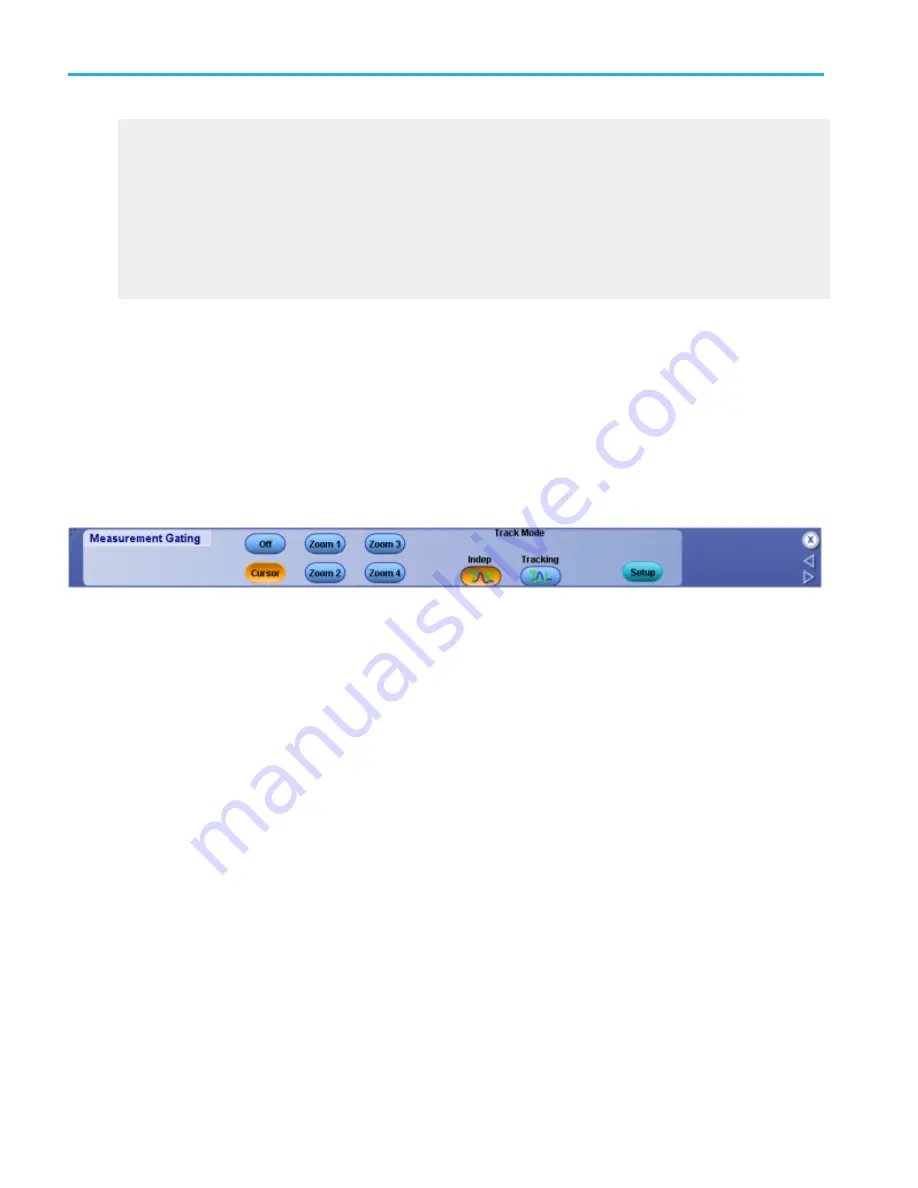
Use the Gating control window to limit the measurement area of the waveform to the region bounded by the vertical bar cursors
or to the left and right edges of a Zoom window.
To use
■
To define the gating area with the vertical bar cursors, click Cursor, and then click either Indep or Tracking to select the
Track Mode. These buttons are only displayed when you click Cursor.
■
To define the gating area from a Zoom area, click one of the four Zoom buttons.
■
To turn off measurement gating, click the Off button.
■
Click Setup to return to the Measurement control window.
Behavior
Normally the instrument takes measurements over the entire waveform record. Gating lets you limit measurements to a specific
portion of the waveform. You can limit gating to the region bounded by the vertical bar cursors or to the left and right edges of a
Zoom area.
When you click Zoom (1–4) the Zoom window appears in the lower half of the display. Measurements are taken within the
boundaries of the Zoom area. You can only take measurements on one Zoom area at a time.
When you click Cursor, measurements are taken within the boundaries of the vertical cursors. Use the multipurpose knobs to
move the cursors.
When you use vertical cursors to control the gating, you can also specify the
. Use the independent cursor mode to
move the cursors one at a time with the multipurpose knobs. Use the tracking mode to have the cursors track one another;
moving Cursor 1 automatically moves Cursor 2 in tandem.
Measurement setups
290
DPO70000SX, MSO/DPO70000DX, MSO/DPO70000C, DPO7000C, and MSO/DPO5000B Series
Summary of Contents for DPO2304SX
Page 1: ...Tektronix Digital Phosphor Oscilloscopes Printable Help P077006219 077 0062 19...
Page 2: ......
Page 3: ...Tektronix Digital Phosphor Oscilloscopes Printable Help www tek com 077 0062 19...
Page 32: ...Introduction xxviii DPO70000SX MSO DPO70000DX MSO DPO70000C DPO7000C and MSO DPO5000B Series...
Page 130: ...Cursor setups 98 DPO70000SX MSO DPO70000DX MSO DPO70000C DPO7000C and MSO DPO5000B Series...
Page 198: ...MagniVu setup 166 DPO70000SX MSO DPO70000DX MSO DPO70000C DPO7000C and MSO DPO5000B Series...
Page 212: ...Display setups 180 DPO70000SX MSO DPO70000DX MSO DPO70000C DPO7000C and MSO DPO5000B Series...
Page 300: ...Math setups 268 DPO70000SX MSO DPO70000DX MSO DPO70000C DPO7000C and MSO DPO5000B Series...
Page 408: ...MyScope setups 376 DPO70000SX MSO DPO70000DX MSO DPO70000C DPO7000C and MSO DPO5000B Series...
Page 510: ...Trigger setups 478 DPO70000SX MSO DPO70000DX MSO DPO70000C DPO7000C and MSO DPO5000B Series...
Page 548: ...Vertical setups 516 DPO70000SX MSO DPO70000DX MSO DPO70000C DPO7000C and MSO DPO5000B Series...
Page 605: ...Utilities DPO70000SX MSO DPO70000DX MSO DPO70000C DPO7000C and MSO DPO5000B Series 573...
Page 606: ...Utilities 574 DPO70000SX MSO DPO70000DX MSO DPO70000C DPO7000C and MSO DPO5000B Series...
Page 920: ...Index 888 DPO70000SX MSO DPO70000DX MSO DPO70000C DPO7000C and MSO DPO5000B Series...


