(Dec., 2013)
STULZ CyberRow Chilled Water Series Installation, Operation & Maintenance Manual
5.3.2.2 Fan Replacement
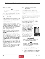
The EC Fans are located behind the front access panel.
The panel must be removed to access the fans. The
fans are equipped with quick connect fi ttings for the
power and control cables to make swap-out easy. Lift
the retaining latch on top of the power and control
cable connector housings to unplug the cables. Cut the
wire-ties holding the cable bundle in the cabinet.
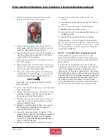
Fan
M-6 Hex Bolts-
Two Per Side
Power/Control
Connectors
Inlet Ring
M-5 Hex Bolts-
Two Per Side
12” Cabinet
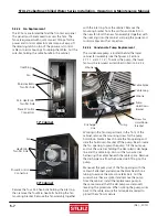
Fan
Hex Bolts-
Two Per Side
Power/Control
Connectors
24” Cabinet
Remove the four M-5 hex-bolts holding the inlet ring
then remove the four M-6 hex-bolts holding the fan
mounting bracket. Remove the fan assembly together
with the inlet ring from the cabinet. Remove the
mounting bracket from the old fan and install it on
the new fan. Bolt the new fan assembly (together with
the inlet ring) into the cabinet and plug the power and
control cables into the connectors.
5.3.2.3 Condensate Pump Replacement
The condensate pump is located behind the lower
cabinet fan assembly (see the fi gures in Sections
2.7.1.1 and 2.7.1.2). To access the pump, the lower
fan must be removed as described in Section 5.3.2.2.
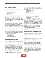
Screw For
Hold-Down
Bracket
Wire-ties
Cable Loop
Discharge
Line
Pump
Pump
Hold-Down
Bracket
Cable Splice
Wire-tie
Working in the fan compartment in the front of the
cabinet, remove the mounting screw for the pump
hold-down bracket. Reach inside the fan opening and
slide the hold-down bracket off the pump. Reach inside
the fan opening to grasp the pump. Tilt the pump up
and cut the wire-ties holding the clear plastic discharge
line and the cable loop. Also cut the two wire ties
harnessing the cables beneath the cable splice. Remove
the discharge line from the barbed stub fi tting on the
pump.
Maneuver the pump out of the fan opening with the
cable still attached and remove the black heat shrink
tubing to expose the wire splice terminals. Cut the
wires where they are spliced and remove the pump
from the cabinet. Install the replacement pump in
the same manner that the old pump was removed,
reversing the procedure. When splicing the pump wires
back to the cable, ensure the terminals are sealed to
protect them from moisture.
5-7

