STULZ CyberRow Chilled Water Series Installation, Operation & Maintenance Manual
(
Dec.
, 2013)
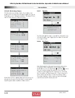
4.5.5.7 Digital
In
Press
Enter
(
)
Key
SERVICE
Options
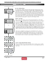
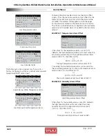
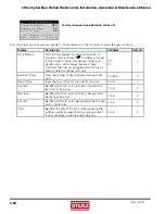
Digital In
Run Hours
CW Digital Inputs
12345678 9101112
pco:CCCCCCCC C C C C
131415161718
C C C C C C
The Service>Digital In screen is provided for information only.
It shows the state of each digital input as either Closed (+24
V) or Open (0 Volts).
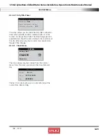
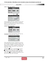
4.5.5.8 Run
Hours
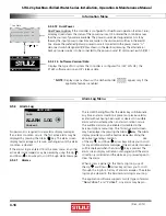
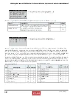
SERVICE
Digital In
RUN HOURS
BMS Comm
Press
Enter
(
)
Key
Starts/Run Hours
CW1 0018hrs
Starts 1
Reset Off
From the Service>Run Hours menu you may access a loop
consisting of the component run hours display screens
applicable to your unit using the
Up ( ) and Down
( )
arrow
keys. Each screen displays the number of run hours and
number of starts logged for the component (i.e. CW valve,
fans, humidifi er, air fi lter changes, etc.). The run hours and
starts may be reset to 0 from the display screens.
The values displayed in each screen are the values logged
since the last time the screen was reset.
4-30
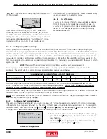
4.5.5.6.8 Work Group Screens
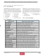
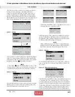
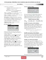
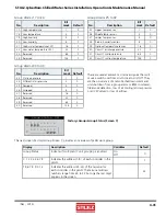
The Service>Group display screens shown below only
appear if two or more units are wired together as a group.
They allow you to confi gure parameters that apply to how
the A/C units interact in the work group.
Group Setup
Unit
ACTIVE
Total in Network
0
Number of Active
0
Lead Unit
0
Capacity Assist
Assist Time
300s
Cooling Cut in
1.0°F
Cut out
0.0°F
Capacity Assist
Humid Cut in
-4.0%
Cut out
0.0%
Dehum Cut in
4.0%
Cut out
0.0%
Group Sensors
Use unit sensors when in
Standby or Assist for
Group Averaging
Temp/Hum Sensors
Yes
Static Pr Sensors
Yes
Group Sensors
Use lead sensor, Avg, min,
or max of group
Temp/Hum:
Local
Static Press:
Local
See Section 4.6 for a detailed description of how work
groups are set up and for information on setting the
operating parameters available in these screens.
Service Menu


