STULZ CyberRow Chilled Water Series Installation, Operation & Maintenance Manual
(
Dec.
, 2013)
4-17
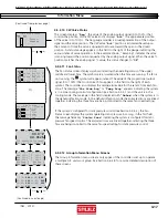
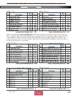
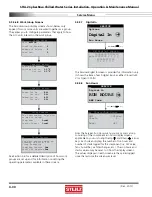
4.5.2.12 Group Information Menu Screens
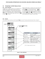
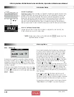
The Group Information menu screens only appear if the controller is set up to operate
a multiple A/C unit work group. See Section 4.6.2.8 for a more detailed description of
these screens.
(Continued from previous page)
Group T/H Sensors
Avg 000.0 °F
000.0 %
Min 000.0 °F
000.0 %
Max 000.0 °F
000.0 %
Min Temp 0
Min Hum 0
Max Temp 0
Max Hum 0
Net T/H Sensors
00.0°F
00.0%rh
T/H Sensor Value Local
Unit 0 of 0 Lead: 1
Group Alarms
1-8:
000
9-16:
000
17-24:
000
25-32:
000
33-40:
000
41-48:
000
49-56:
000
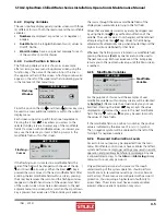
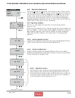
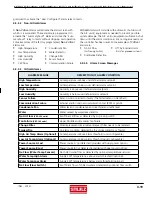
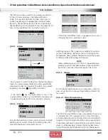
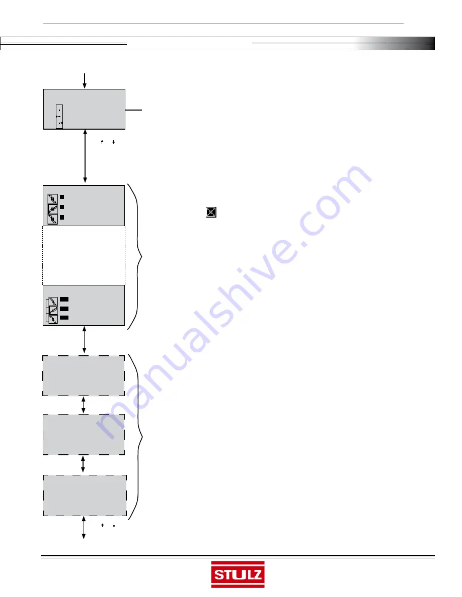
If the system is confi gured for static pressure control (see Section 4.4.4.2), the Fan
Status screen displays the current operating static pressure in m.i.w.g. in the fi rst fi eld.
The message fi elds say "
Static Pres
" indicating the system is confi gured for static
pressure fan speed control. The animated icons are linked together indicating the three
fans are being controlled to the same fan speed setting for static pressure control.
4.5.2.11 Fan Status
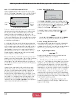
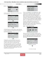
The Fan Status screen displays symbols indicating the operating status of the upper,
middle and lower fans. The symbols are animated when the fans are running. If a fan is
not running, the
symbol will appear instead. The value of the proportional output
signal (0 to 100%) that controls each fan appears in the fi eld to the right of each
symbol. The controller also displays the temperature value for the sensor from each fan
zone. The message "
Var from Avg
" or "
Temp Prop
" appears indicating the system
is in a zone cooling control confi guration (see Section 4.4.4.1) and the unit is in the
cooling mode. The message in the fi eld is replaced with "
Dehum
" when the system is in
the dehumidifi cation mode. In the dehumidifi cation mode the animated icons are linked
together indicating the three fans are being controlled to the same fan speed setting.
Fan Status
10.0%
Var frm Avg 000.0°
F
10.0%
Var frm Avg 000.0°
F
10.0%
Var frm Avg 000.0°
F
Or,
Fan Status
Pressure: 100miwg
30.0%
Static Pres
30.0%
Static Pres
30.0%
Static Pres
Press ( ) or ( ) Key
(Continued on next page)
Information Menu
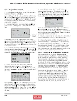
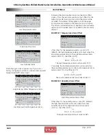
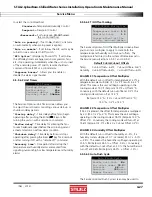
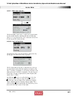
This screen displays "
Req
", the value of the analog output signal (0 to 100%) that
controls the position of the CW valve and it displays "
Act
", the approximate position
of the valve (0 to 100%). The bar gauge provides a visual representation of the output
signal and the valve position. The CW valve "
Act
" position is estimated based upon
the amount of time the valve is signaled to actuate toward the open or the closed
position. A status message appears in the fi eld to the right of the gauge indicating the
various states of valve operation. In the example shown, "Ramping" indicates the valve
is moving toward the position requested by the analog output signal. When the valve %
position matches the analog signal % value, the status changes to "
OK
"
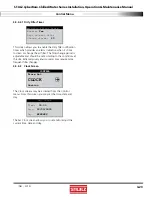
4.5.2.10 CW Valve Status
Press ( ) or ( ) Key
CW Valve Status
Req Act
50% 25%
Status:
Ramping


