(Dec., 2013)
STULZ CyberRow Chilled Water Series Installation, Operation & Maintenance Manual
1-6
maintenance is performed. The handle of the switch
may be locked in the “Off” position to prevent
unintended operation.
1.5.2 Circuit Breakers/Motor Start Protectors
CyberRow units incorporate state of the art component
protection with the use of motor start protectors and
circuit breakers. If an overload occurs the switches
must be manually re-set after the overload condition is
cleared.
1.5.3 Coil(s)
Cooling coils are aluminum fi nned/copper tube
construction. The coils are leak tested and cleaned
before installation by the factory. Condensate drain
pans are provided to collect water condensed by the
coils. The drain pans are emptied by a condensate
pump that directs the water to a pipe stub located
either at the top or the bottom of the A/C unit
depending on the piping confi guration (see Sections
2.7.1.1 and 2.7.1.2).
A fl oat switch is placed in the lower condensate pan
to detect if the water level rises. If the condensate pan
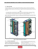
Figure 2- Typical Internal Layout- CRS-180-C
NOTE:
1. CABINET ACCESS PANELS REMOVED TO SHOW INTERNAL PARTS.
DRAIN PANS
LEVEL ADJUSTMENT
SCREW (4)
CONDENSATE
PUMP
EC FAN (3)
HINGED ELECTRIC BOX
COVER
DISCONNECT
SWITCH
COIL
AIR FILTERS
SUPPLY / RETURN PIPE
TRANSITION PLATE
T/H SENSOR
CASTER HOUSING
(4)
TEMPERATURE SENSORS
(HIDDEN FROM VIEW)
CW VALVE
HUMIDIFIER
HUMIDIFIER DRAIN
PUMP
FLOAT SWITCH
fails to drain, the fl oat switch signals the controller to
annunciate an alarm.
1.5.4 Condensate Pump
A condensate pump is factory installed in the lower
drain pan. The pump automatically eliminates
condensate water from the drain pan. The pump has an
internal fl oat switch which turns the pump on and off
based on the water level.
1.5.5 EC Fans
The unit is equipped with three high effi ciency,
Electronically Commutated (EC) fans. EC fans utilize a
brushless motor equipped with permanent magnets
and permanently lubricated ball bearings. The fan
impellers are backward curved and attached to the
rotor casing. The fan is balanced and aerodynamically
optimized to minimize vibration.
The fans do not utilize drive belts. Fan speed is variable
via a 0 to 10 VDC signal from the system controller.
The fan motor is equipped with integral electronics and
does not require the addition of secondary electronics
such as thermal protection, inverters or fi lters. The fan


