STULZ CyberRow Chilled Water Series Installation, Operation & Maintenance Manual
(
Dec.
, 2013)
4-12
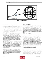
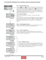
Figure 13- Dewpoint Control
Cool Only- No
Humidifi cation
Needed
Actual
Temp/RH
(Dewpoint)
Setpoint
Psychrometric Chart
4.4.3.2 Humidifying
If this option is selected (available on CRS-180 units only),
an on-board steam humidifi er may be turned on or off by
the controller to maintain relative humidity to a control
setpoint. Once the controller enables humidifi cation, the
humidifi er will operate at 100% capacity until the humidity
setpoint is reached. An on-board control module manages
the humidifi er operation, i.e. humidity production, fi ll cycles,
drain cycles.
4.4.3.3 Dehumidifying
When dehumidifi cation is called for the fan speed
automatically changes to the dehumidifi cation fan speed
setting. The controller will operate the system in the
cooling mode at full output to strip moisture from the air.
In a CW system the control valve may be set to be less
than 100% open for dehumidifi cation if desired in the
Service>Humidity menu (see Section 4.5.5.2). The system
will remain in the cooling mode until the actual relative
humidity (or dewpoint) reaches the control setpoint plus the
dehumidifi cation cut-out offset. If the control temperature
drops below the low temperature cut-out setpoint for the
dehumidifi cation mode (temperature setpoint minus 4°F
default), cooling operations will be stopped.
4.4.4 Air Flow/Fan Speed Control
The
E²
controller treats each EC fan as a variable speed
fan. The controller manages the speed of each fan from a
factory-set minimum up to a factory-set maximum speed.
The minimum fan speed is used whenever the A/C unit has
no cooling operations running. The maximum fan speed
setting is used during times when the A/C unit is cooling
4.4.3 Operating
Confi gurations
The operating confi guration for the controller depends on
what type of air conditioner is being controlled (i.e. AR,
CW, W/G) and what features are selected. The operating
confi guration is preset by the factory according to the
application. If certain features discussed in this manual are
not factory enabled, no screens for that feature will appear
in the controller user interface display.
4.4.3.1 CW
Cooling
Upon a call for cooling the controller activates a chilled
water control valve with a proportional/integral (P/I),
0-10 VDC signal. The valve opens proportionally to the
demand for cooling based on air temperature. The control
settings include a setpoint and a control dead band. The
cooling band is adjustable from 0-10°F in the Factory
menu. Contact STULZ Technical Support for guidance if
adjustment is needed.
When the control air temperature exceeds the programmed
setpoint plus offset, the CW valve is opened allowing CW
to fl ow to return the air temperature to the setpoint and
maintain it. If the control air temperature continues to rise,
the chilled water valve position continues to modulate
open as needed, up to 100% (fully open), to maintain the
temperature setpoint.
The control output is matched to the valve. If the valve
typically opens at 2.5 VDC, the control I/O module will
generate the appropriate voltage for opening the valve
starting at the minimum voltage of 2.5 VDC. From there
the signal increases as needed until the valve position
reaches 100% open.

