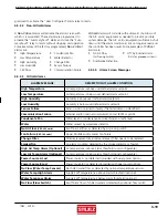
STULZ CyberRow Chilled Water Series Installation, Operation & Maintenance Manual
(
Dec.
, 2013)
4-33
4.6 Communication With The Controller
It is possible for the
E²
controller to communicate in
multiple ways. The controller may be set up to utilize a
pLAN network to link with additional
E²
controllers to
create a work group consisting of multiple A/C units (see
Figure 15 and Section 4.6.1).
Using an optional BMS interface port, the unit may also
be connected to a BMS for monitoring and control of data
points using a multitude of different serial communication
protocols (see Section 4.7).
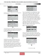
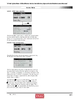
Figure 15- Confi guring Multiple A/C Units
Up to 8
E²
Series
Controllers in
Work Group
A/C Unit #2
Control Variables
From
BMS
Lead
Controller-
A/C Unit #1
Temperature Sensor*
Humidity Sensor*
A/C Units
#3 - #8
pLAN
Connection
* Proportional Input
Signals From Sensors or
BMS Analog Output.
Temperature Sensor*
Humidity Sensor*
Temperature Sensor*
Humidity Sensor*
4.6.1 Work Group Set-up
The controller may be networked with a group of A/C unit
controllers via an RS-485 pLAN connection to manage their
outputs as a system in an N+M (M = number of standby
units) group. The controllers from up to seven additional
A/C units may be tied to a Lead controller. The number of
units to be assigned as Active, Capacity Assist or Standby
duty is to be confi gured by the factory, however, they may
be reconfi gured in the fi eld. A unit may also be designated
as "Out of Service".
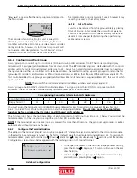
The Main screen of each unit in the work group will
indicate that unit's duty assignment in the bottom fi eld. If
the controller is the group lead, it will be indicated in the
bottom fi eld also.
01/01/09 00:00:00
00.0°F
00%rh
dp 00.0°F
Unit On
ACTIVE
Lead
Multiple Unit Display Screen
One controller may be designated as the work group lead
and networked with the controllers from a series of up to 7
additional A/C units. If confi gured for multi-unit operation,
the work group lead controller display panel allows access
to the same data and group control sensor choices that are
available from networked system controller display panels.
4.6.1.1 Standby
If the lead controller in the work group loses a signal
acknowledgement from an active A/C unit in the group,
that A/C unit is deemed as failed or taken out of service.
The failed unit will be replaced with the fi rst available
standby unit from the work group. The standby unit is
cycled on and designated as the new active unit.
4.6.1.2 Capacity
Assist
The Capacity Assist option can be used to maximize
effi ciency for conservation of energy and to more precisely
control capacity at low demand. This feature enables Active
A/C units to handle the demand up to a certain temperature/
humidity setpoint and then enables additional units to begin
operating as needed. If the Active A/C units are running and
unable to satisfy the demand, Capacity Assist A/C unit(s) are
programmed to turn on to assist the Active units.
Each Capacity Assist unit may be set to control operation
based on it’s local temperature/humidity sensor values
or on network sensor values transmitted from the lead
controller. Multiple Capacity Assist units are typically
set with each unit in the group assigned incrementally
increasing/decreasing offsets for cooling, humidifying and
dehumidifying so they will turn on one at a time only if the
unit(s) currently operating are unable to satisfy the demand.
They should incrementally turn off as each unit reaches
it's cut-out setpoint, while active A/C unit(s) continue to
maintain room conditions at the desired level.
4.6.1.3 Unit
Rotation
In this mode, the lead controller will rotate duty between
the grouped A/C units to promote equal run time and
will rotate the role of group lead. When set up for unit
rotation, the A/C units will rotate duty in order of their
group addresses. Active, Capacity Assist and Standby units
are all in the rotation cycle so even a standby unit will be
cycled into active duty on a scheduled basis. A/C units in
the group may have their duty assignments locked so they
do not join the rotation cycle. In this case the message

