STULZ CyberRow Chilled Water Series Installation, Operation & Maintenance Manual
(
Dec.
, 2013)
4-14
(switch or relay). In an emergency, the circuit may be
opened to disconnect control power from the A/C unit
to stop operation, bypassing delay timers so the chilled
water valve, fans, etc. stop immediately. The A/C system
will automatically turn back on when the Emergency Power
Off (EPO) switch contacts are closed. Refer to the electrical
drawing included with the A/C unit for the wiring details.
NOTE
The EPO disconnects control power from the unit
contactors causing them to open. MAIN POWER
IS STILL PRESENT IN THE UNIT WHEN THE EMER-
GENCY STOP SWITCH IS OPERATED.
4.4.6 Remote On/Off Control
Terminal positions are provided to connect a remotely
located, On/Off switching control device. If the A/C unit is
turned on and the
E2
controller receives a remote input
signal to turn off the A/C unit, the controller disables all
control outputs and a message "Off by Remote Shutdown"
appears in the main display screen. The A/C system will
automatically be re-enabled when the remote On/Off signal
calls for the A/C unit to turn back on. Refer to the electrical
drawing included with the A/C unit for the wiring details.
4.4.7 Dual Power Transfer Monitoring
As an option, two sources of input power may be utilized
(see Section 1.6.5). With this feature the controller
monitors switching between two power sources, such as
commercial power and generator backup. Each power
source is monitored by a voltage monitor (
used on
1-phase systems
) or a phase relay (
used on
3-phase
systems
), one output of which goes into the power
switching circuit and the other output sent to the controller
for monitoring purposes. Should a power transfer occur,
the controller provides an alarm message and the alarm
display indicates which power source failed.
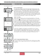
4.5 Menu
Screens
4.5.1 Main
Menu
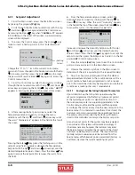
MAIN MENU
Factory
INFO
Alarm Log
The Main Menu is accessed from the Main screen by
pressing the
Prg
key. The Main Menu screen provides a
complete listing of the menu loops that are available. You
may scroll through the menu categories using the Up ( )
and Down
( )
arrow keys. From the Main Menu screen you
may select from among the following standard menus:
"Info"
- Displays basic read-only status information.
Allows you to monitor system operational parameters. No
password is needed at this level.
"Alarm Log"
- Displays all alarms and "power-ups" in
sequential order with a time and date stamp. No password
is needed at this level.
"Control"
- Allows modifi cation of basic control parameters
such as set points and clock. Level 1 password is needed to
enter this menu.
"Service"
-
Allows modifi cation of advanced control
parameters such as offsets, fan speed, BMS set up and permits
the user to save customer parameters and reset the controller
to the customer or factory default values. Level 2 password is
needed to enter this menu.
"Factory"
- Allows modifi cation of more advanced control
parameters such as sensor scaling, start-up delays and
grouping parameters. Level 3 password is needed to enter
this menu. Entry to the Factory menu is intended for
qualifi ed technicians.


