STULZ CyberRow Chilled Water Series Installation, Operation & Maintenance Manual
(
Dec.
, 2013)
enable a periodic fl ushing of the CW coils with the control
valve open at 100%. This is used to remove any sediment
that may have collected.
If enabled, you may set a minimum valve opening threshold
below which a periodic fl ush cycle is required. That is, if the
control valve position ever exceeds the percentage entered
since the last fl ush cycle, the scheduled fl ush cycle will be
skipped and a new interval will begin. If the valve does not
4-28
Service Menu
reach the minimum open position entered, a fl ush cycle will
occur when the interval since the last fl ush cycle expires.
The interval between fl ushes may be varied from 1 hour to
720 hours (30 days). The duration of the fl ush cycle may
be varied from 30 to 300 seconds. The number of fl ushes
displayed at the bottom of the screen is the total number of
fl ush cycles since the A/C unit was initialized.
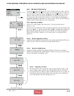
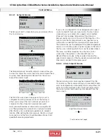
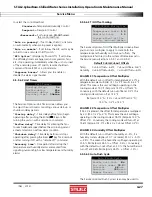
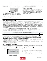
4.5.5.6.5 Custom Setup
Custom Setup
Setup the alarm text,
custom alarms, and
any custom sensors.
CUSTOM
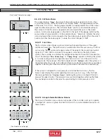
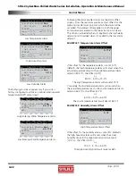
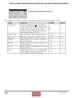
4.5.5.6.6 Customer Alarm Input
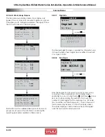
If enabled, a customer provided alarm input may be used to activate the Summary Alarm relay and show a specifi c Customer
Alarm message in the alarm display screen. A Customer Alarm message may simply be displayed as "
CUSTOMER ALARM 1
"
as shown below, or you may press (
) and use the ( ) and
( ) arrow keys to construct a specifi c alpha/numeric message in
the fi eld stating the specifi c alarm condition in your own terms; i.e. "
GAS DETECTION
", "
INTRUSION ALARM
", etc. The
Customer Alarm message may be set up on one line with up to 20 characters.
Customer Alarm3 Text
CUSTOMER ALARM 3
Customer Alarm2 Text
CUSTOMER ALARM 2
The controller may be equipped with up to 2
additional Customer Alarms as an option.
Customer Alarm Text
CUSTOMER ALARM 1
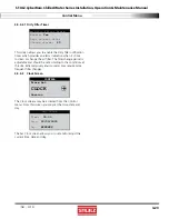
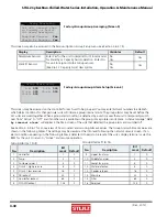
4.5.5.6.7 Custom Alarm Setup
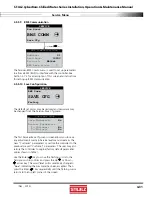
The
E²
controller may activate a Custom Alarm output and energize a designated N.O./N.C. relay. A custom alarm output is
set up by adding the binary bitmask numbers assigned to the specifi c alarms and signal failures you wish to monitor via the
relay and then entering them in the Custom Alarm Setup screen.
Custom Alarm Setup
1-8:
8
9-16:
10
17-24:
0
25-32:
18
33-40:
0
41-48:
0
Custom Alarm 2 Setup
1-8:
000
9-16:
000
17-24:
000
25-32:
000
33-40:
000
41-48:
000
49-56:
000
57-64:
000
65-72:
000
73-80:
000
Custom Alarm 3 Setup
1-8:
000
9-16:
000
17-24:
000
25-32:
000
33-40:
000
41-48:
000
49-56:
000
57-64:
000
65-72:
000
73-80:
000
The controller may be equipped with up to
2 additional Custom Alarms as an option.
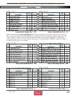
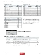
You can select any mix of the
48 alarm variables as shown in the tables that follow. As an example, for a custom alarm based
only on the occurrence of moisture alarm, condensate pan, pump, failure of the return humidity sensor you would enter the
following bitmask values for the applicable alarm numbers and enter 0 for the rest:
Custom Alarm number 1 - 8...............Moisture alarm (No. 4) =
8
Custom Alarm number 9 - 16.............Fire/smoke (No. 10) + Condensate pan (No. 12) =
10
(2+8)
Custom Alarm number 25- 32............Middle temp. sensor (No. 26) + Return humidity sensor (No. 29) =
18
(2+16)
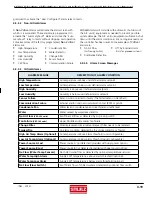
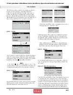
The custom alarms are set up by entering the bitmask totals developed from the following tables:
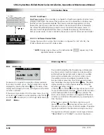
From the Service>Options>Custom Setup screen you may press the Enter (
)
key to access a menu loop to set up custom alarm features. Any controller alarm
or signal failure will activate the summary alarm output. Upon receiving an alarm
indication, the user may press the alarm key and call up alarm screen messages.


