STULZ CyberRow Chilled Water Series Installation, Operation & Maintenance Manual
(
Dec.
, 2013)
4-3
4.1.3 Controller I/O Module
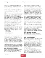
The controller is a microprocessor based I/O module mounted
inside the A/C system electric box (see Figure 9). The controller
I/O module contains the software that manages the operating
parameters of the A/C system.
1
2
4
3
6
5
7
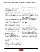
Figure 9- Controller I/O Module
4.1.3.1 Controller I/O Module Layout
The controller I/O module contains the logic and input/
output terminals. See Figure 9 for details of the controller
I/O module layout. The item numbers that follow coincide
with the call-outs in Figure 9.
1. Connection (J10) for interface display panel
2. RS-485 connection for pLAN (J11)
3. Hatch for BMS or network card
4. Power on LED (Yellow)
5. Signal LEDs (Red, Yellow, Green)
6. Hatch for expansion I/O module(s)
7. Power connector (J1)
4.1.4 BMS
Interface
The
E2
series controller may incorporate a BMS network
card with a communication port (Figure 10). This can be
fi eld connected through a RS-485 serial interface to a
Building Management System via Modbus, BACnet, SNMP
or HTTP protocol as confi gured by the factory. A controller
interfaced to a network must be confi gured for BMS
communication.
BACnet IP, BACnet Ethernet,
HTTP, SNMP, & Modbus IP
BACnet MS/TP
Modbus RTU
Figure 10- BMS Interface Ports

