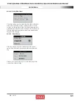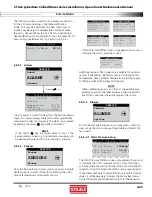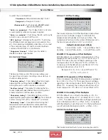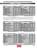
STULZ CyberRow Chilled Water Series Installation, Operation & Maintenance Manual
(
Dec.
, 2013)
4-18
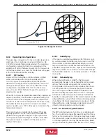
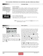
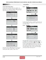
4.5.3 Alarm
Log
MAIN MENU
Info
ALARM LOG
Control
No password is required to view alarm display messages.
If an alarm condition occurs, the fi rst active alarm may be
displayed by pressing the Alarm ( ) key. The alarm screen
display text message will remain unchanged until the alarm
condition is cleared.
If the alarms log is entered from the main menu, any other
active alarm message(s) may be viewed by using the Up ( )
and Down
( ) arrow keys to scroll through alarm messages.
4.5.3.1 Alarms
The red LED backlight within the alarm key will illuminate
any time an alarm condition is present or previous alarms
existed without having been reset or cleared. An audible
alarm will also activate when an alarm condition occurs.
The audible alarm may be enabled or disabled in the
Service>Options menu loop. The fi rst active alarm screen
may be displayed by pressing the Alarm ( ) key. The Alarm
display provides you with a text message describing the
abnormal operating condition. Use
of the Up ( ) and Down
( ) arrow keys allows you to scroll
for any additional alarm messages. Only active alarm screens
will be displayed when the Alarm ( ) key is pressed. The
alarm screen display will remain unchanged until the alarm
condition is corrected and the alarm key is pressed again to
clear the alarm.
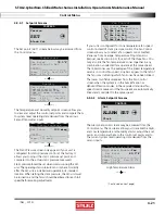
When access is gained to the Alarm Log loop, use of
the Up ( ) and Down
( ) arrow keys allows you to scroll
through the log for a history of alarm messages. The alarms
log may be cleared in the Service>Alarm log menu loop.
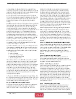
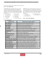
The application software supports two (2) types of alarms,
“Non-Critical
” and “
Critical
”. Any alarm may be pro-
Dual Power
A/Preferred power OK
B/Alternate power OK
Press ( ) or ( ) Key
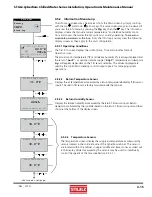
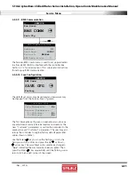
4.5.2.13 Dual Power
Dual Power option.
If the controller is confi gured for Dual Power operation (Section 1.6.6),
a display screen shows the status of the power sources. OK indicates the controller senses
that the sources of power are available. The power sources are designated as A or B by
the way the input power connections are made to the disconnect switches in the electric
box. Ensure the preferred (primary) power source is connected to the power source "A"
disconnect switch designated (Q80) as shown in the electrical drawing. The alternate (or
back up) power source is to be connected to the power source "B" disconnect switch (Q81).
* See Note
*
NOTE:
Display screens shown with a dashed border
appear only if the
applicable feature is enabled.
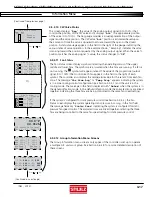
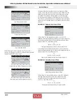
4.5.2.14 Software Version/Date
Displays the type of A/C system the controller is confi gured for (CW, WG AR), the
STULZ software version and it's release date.
1 CW-24" CyberRow
E2C V: 1.3
10/14/13
STULZ
Information
Menu
Alarm
Log
Menu

