(Dec., 2013)
STULZ CyberRow Chilled Water Series Installation, Operation & Maintenance Manual
5-5
5.3 Field Service
NOTE
Do not attempt to make repairs without the
proper tools.
NOTE: Repairs to refrigeration systems must be per-
formed by a journeyman refrigeration mechanic or air
conditioning technician.
5.3.1 CW System
If the Chilled Water system isn’t cooling or if cooling
is reduced, check for leaks in the system. Check for
clogged water lines. If strainers are installed in the
CW lines, check the condition of the fi lters. Clean or
replace the fi lters if necessary.
In situations where scaling could be heavy, untreated
water in the unit cooling coils may cause, over a period
of time, a loss of heat exchange capacity due to a min-
eral deposit build-up inside the coil. Only a qualifi ed
service mechanic should clean dirty coils.
5.3.1.1 Leak
Detection/Repair
A leak in a chilled water cooling system will usually
form a puddle of fl uid beneath the unit that can be
easily seen.
When a leak is detected, turn off the CW supply
before attempting repairs. Adjacent piping must be
thoroughly cleaned by removing all paint, dirt and oily
fi lm. Use wire brush, sandcloth or sandpaper and wipe
the area with clean, dry cloths. Protect nearby parts
from heat damage by wrapping with water-soaked
cloths.
For copper-to-copper (piping) repairs use SILFOS Alloy.
No fl ux is required with Silfos Alloy. Silver solder (Stay
Silv #45) and fl ux are to be used on copper-to-brass or
copper-to-steel repairs.
When repairs are completed, remove all traces of fl ux.
After any repair, pressurize the system to check for
leaks prior to recharging the system.
5.3.2 System Repairs/Component
Replacement
Turn off power to the unit at the main power
disconnect switch when repairing, removing and
replacing components. Ensure power is turned back on
at the main power disconnect switch after repairs are
completed.
All electrical connections should be checked to ensure
they are tight and properly terminated. Check all circuit
breakers, contactors and wiring. The contactors should
be examined and replaced if contacts are worn or
pitted.
5.3.2.1 Humidifi er Cylinder Replacement
Remove the rear access panel from the CyberRow
cabinet to access the humidifi er.
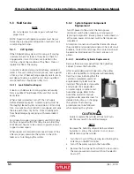
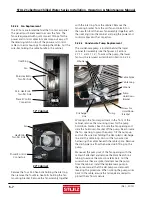
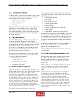
After an extended period of operation, the yellow
LED on the humidifi er control panel will repeatedly
fl ash four times indicating that the
cylinder is completely used and
a replacement cylinder must be
installed. The cylinder is disposable
and cylinder life is dependent
on water supply conditions and
humidifi er usage. Refer to the
humidifi er operator’s manual
supplied under separate cover for
detailed instructions on changing
the cylinder. The following
procedures are to be followed
when replacing the cylinder.
CAUTION
Failure to replace the cylinder at the end of cylin-
der life may result in humidifi er damage.
NOTE
Decrease the humidity setpoint below ambient
humidity to allow the cylinder to cool down
before removing the cylinder.
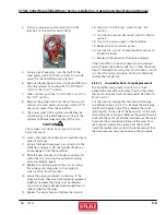
1. Turn the A/C unit Off by pressing (and holding) the
Enter key on the
E²
controller.
2. Turn off the water supply to the humidifi er.
3. Remove the front panel from the A/C unit and turn
the main power disconnect switch on the electric
box to Off.


