STULZ CyberRow Chilled Water Series Installation, Operation & Maintenance Manual
(Dec., 2013)
2-6
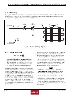
For pipe connection sizes, refer to the following table:
PIPE CONNECTION SIZES
Chilled Water Condensate
Model #
Inlet/Outlet Drain
CRS-090-C
1 1/4”
1/2”
CRS-180-C
1 1/2”
1/2”
NOTE
Use standard refrigeration practices for piping,
leak testing and fi lling the chilled water circuit.
The piping should be isolated by the use of vibration
isolating supports. Provide supports (clamps or hangers)
as necessary every 5 to 10 feet along piping runs to
minimize vibration and noise transmission. To reduce
vibration transmission and prevent pipe damage, seal
openings in walls using a soft fl exible material to pack
around the piping. After the piping is installed, seal the
gaps between the pipes and the cabinet entrance holes
so air won’t leak around the pipes.
NOTE
Chilled water lines should be insulated to prevent
condensation from forming on the pipes if
ambient dew point temperatures are higher than
the fl uid temperatures.
CAUTION
After the interconnecting piping is installed, the
entire piping circuit must be thoroughly fl ushed
prior to operating the system.
If newly installed CW supply and return piping is used,
it is recommended that the piping system be cleaned
prior to connecting it to the unit.
If solvents/cleaning
solutions are used, ensure they are completely
fl ushed from the piping before connecting it to
the unit.
Failure to do so could result in equipment
problems.
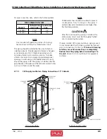
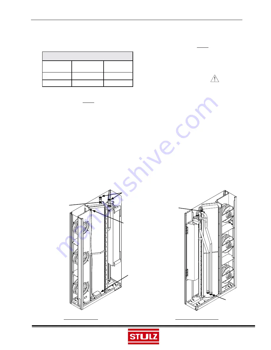
2.7.1.1 CW Supply and Return Piping Connections- 12” Cabinets
FEMALE PIPE
THREADS
CONDENSATE DRAIN-
1/2” FPT
SCHRADER
VALVE
PUMP
SCHRADER
VALVE
MALE PIPE THREADS
TOP
ACCESS
PIPING
BOTTOM
ACCESS
PIPING

