background image

MV-805 IP Multiviewer User Manual

 Software Upgrade 

Maintenance 10.1

Issue1 Revision 1

Page 127

© 2018 SAM

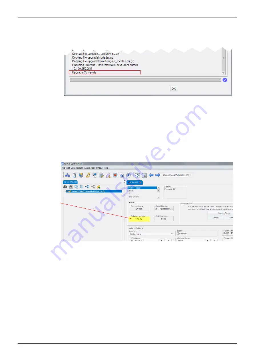
13. The software upgrade is done when the Upgrade log messages say “Upgrade 

Complete”, see Figure 111. This will take 2 to 3 minutes.

14. After: 

the module has rebooted, 

and the upgrade is complete, 

and SAM RollCall Control Panel has reconnected to the unit, 

then the RollCall 

System-Setup

 template can be displayed and it will now show the 

new upgraded software version number, see Figure 112. 

Figure 111 Software Upgrade Complete 

Figure 112 Software Version on System-Setup Template

Software Version

Summary of Contents for MV-805

Page 1: ...www s a m com User Manual MV 805 IP Multiviewer Software based Turnkey IP Multiviewer Unit...

Page 2: ...ion 7 3 Product Overview 12 4 Unit Hardware 25 5 Hardware Installation 38 6 RollCall Templates 46 7 Getting Started 1 Unit Settings RollCall Template 77 8 Getting Started 2 IP Routing Orbit 89 9 Getti...

Page 3: ...ignal Selection 18 3 4 1 MV 805 and SAM IP Routing System 18 3 4 2 Non SAM IP Routing 19 3 5 Network Topologies 20 3 6 Video Timing Reference 22 3 7 Software Compatibility Matrix 22 3 8 Configuration...

Page 4: ...nnect RollCall Control Panel to the MV 805 unit 78 7 1 1 Preparation 78 7 1 2 Connecting RollCall Control Panel 78 7 2 Initial MV 805 Unit Configuration with RollCall 81 7 2 1 Setting Up the Host Name...

Page 5: ...fying Multiviewer TSL Tally Mode 117 9 4 3 Specifying Index Parameters for each UMD 118 9 5 On screen Input Status Information Lines 120 10 Maintenance 121 10 1 Software Upgrade 121 10 1 1 The Upgrade...

Page 6: ...enerated from the software programs which are displayed on the screen such as icons screen display looks etc Information in this manual and any software are subject to change without notice and does n...

Page 7: ...un sistema de alimentaci n con conexi n a TIERRA y teniendo una conexi n neutra f cilmente identificable La toma de alimentaci n para la unidad debe ser cercana y f cilmente accesible ESP Advertencia...

Page 8: ...oimenpiteit kuin mit k ytt ohjeissa on neuvottu ellet ole asiantuntija Voit saada s hk iskun J t kaikki huoltotoimet ammattilaiselle S hk iskujen v ltt miseksi suojaa laite sateelta ja kosteudelta Var...

Page 9: ...pplies throughout this document including safety warnings and advice 2 1 2 Safety Warnings CAUTION These servicing instructions are for use by qualified personnel only To reduce risk of electric shock...

Page 10: ...ains disconnection devices for this unit To reduce the risk of electric shock plug each power supply cord into separate branch circuits employing separate service grounds LASER SAFETY The average opti...

Page 11: ...wer Cords Power cords are supplied to suit the geographical region 2 3 Safety and EMC Standards Safety Standards Refer to Section A 5 Regulatory Compliance on page 130 for safety information EMC Stand...

Page 12: ...tiple video IP streams are processed video and audio status is monitored and multiviewer video wall output image s are formed by the MV 805 The MV 805 provides a high resolution display output video I...

Page 13: ...uality uncompressed Video IP stream outputs 1080p 4K 50 59 94 60 Hz Total Multiviewer Wall Layout Flexibility Up to 32 video tiles per display Display status and alarms from video inputs and or extern...

Page 14: ...e1 Revision 1 Page 14 2018 SAM 3 2 Order Codes Order Code Description MV 805 32 MV 805 32 1RU Software based Turnkey IP Multiviewer MV 805 16 MV 805 16 1RU Software based Turnkey IP Multiviewer QSFPCO...

Page 15: ...gh performance Media IP network ports Up to two control network ports Power Up to two AC power connections The MV 805 unit is IP in and IP out and must be connected to a media IP routing system All th...

Page 16: ...s a video IP stream to the media IP network interface Figure 3 shows the connection of the MV 805 s multiviewer software application to the unit s external interfaces Destination Spigots Each input sp...

Page 17: ...hus there are two identical Multicast IP streams available The receiving destination spigots use both IP streams to re form the original IP stream using the first data packet to arrive from fabrics A...

Page 18: ...ry multicast IP stream and the corresponding destination spigot can then gather its new multicast data packets Note SAM IP Routing System IP Routing System Controller IP RSC Unit SAM offer an IP Routi...

Page 19: ...19 2018 SAM 3 4 2 Non SAM IP Routing For non SAM IP routing systems a SAM IQTIC modular card is required by the MV 805 to translate SAM protocols into an external third party control SDC 01 The user m...

Page 20: ...SAM 3 5 Network Topologies The 1RU turnkey MV 805 uses out of band control Network topologies suitable for MV 805 include those described in Figure 6 to Figure 8 Figure 6 Network Topology One Media I...

Page 21: ...MV 805 IP Multiviewer User Manual Network Topologies Product Overview 3 5 Issue1 Revision 1 Page 21 2018 SAM Figure 8 Network Topology Two Media IP Fabrics A and B Two Control Networks...

Page 22: ...tiviewer project See Section 6 RollCall Templates on page 46 See Section 7 Getting Started 1 Unit Settings RollCall Template on page 77 3 8 2 Unit IP Routing Settings in the IP Routing System The SAM...

Page 23: ...ated as an identifier by SAM Orbit The name may be changed with the Edit Name control in the home screen Projects with the same name are considered to be the same and SAM Orbit warns the user if there...

Page 24: ...ure 9 IP Networks for a MV 805 Turnkey Unit a Rear Network Connections b Data Packet Types Media Fabric IP Networks Media IP IGMPv3 Join Requests Control IP Networks Multiviewer Control messages RollC...

Page 25: ...ve useful should it ever be necessary to transport or ship the equipment 4 Always read the installation and the user instructions carefully it will provide you with helpful hints and tips about care a...

Page 26: ...trol panel comprising some push buttons and some LED indicators There are two drives fitted SSDs On the rear there are two AC power inlets and an array of network control and data signal connectors Th...

Page 27: ...Chassis Mounting ears One each side 2 5 Hard Drive Bays Front Control Panel see sub section 4 3 1 Front USB Connectors Handles One each side Caution Only use handles to slide unit into out of a rack 2...

Page 28: ...nit is powered down Flashing Green Flashes on Network activity Chassis LAN 2 LED Chassis ethernet LAN 2 interface Right hand LED Network interface identifier Control eno1 Green On Network connection m...

Page 29: ...it but standby power is still supplied to the unit Push button for 3 to 5 seconds to begin a power up down of the unit WARNING Unplug BOTH mains cords before servicing the unit LED Control Indicator C...

Page 30: ...5 SSDs are fitted into removable hard drive bays each with two status LEDs LED Indicator Color Status Activity LED Green SSD installed Flashing Green SSD I O Activity Status LED Red Failed Hard Drive...

Page 31: ...b Annotated Rear Panel PSU Modules and AC Power Inlets see 4 4 1 Expansion Slots see 4 4 3 Server Motherboard I O see 4 4 2 a Rear panels b Annotated rear panel MV 805 32 shown MV 805 32 MV 805 16 MV...

Page 32: ...igure 16 MV 805 Rear AC Power Inlets LED Description Green Power Supply Unit PSU is on and operating Amber Power Supply Unit is turned off but is connected to a live mains voltage supply Red Power Sup...

Page 33: ...Description VGA Port VGA Not used in normal operation Console VGA output See Note 1 USB Port 0 3 USB Type A Not used in normal operation USB 3 0 ports See Note 1 LAN 2 RJ45 Chassis ethernet port LAN 2...

Page 34: ...Link Speed LED Left hand side LED Off 10 Mb s link speed established Green 100 Mb s link speed established Amber 1 Gb s link speed established Activity LED Right hand side LED Amber Blinks on when the...

Page 35: ...ght hand QSFP28 cage 100 Gb Ethernet Must be fitted with a suitable QSFP28 module and connected to a Media IP Fabric A B Table 8 MV 805 Media IP Fabric Interfaces LED Indicator Color Status Link Statu...

Page 36: ...erfaces should be connected to media IP fabrics and are used for the real time media IP streams etc There are two media IP Fabric interfaces on an MV 805 16 There are four media IP Fabric interfaces o...

Page 37: ...unit configuration with the RollCall templates external physical network interfaces can be mapped to any of the internal multiviewer s IP fabric connections External Physical Network Interface Interna...

Page 38: ...rating Environment on page 130 Install the equipment in a clean dust free environment that is well ventilated Avoid areas where heat electrical noise and electromagnetic fields are generated A moderat...

Page 39: ...are mounted inside the chassis Figure 20 shows the chassis cooling ventilation air flow Note Please refer to the third party manufacturers for information on Chassis ventilation and Fan maintenance F...

Page 40: ...hysical on page 129 for the unit s depth dimensions The following precautions should be observed 1 Do not obstruct the front of the chassis The whole front is a cooling air intake for the chassis 2 Do...

Page 41: ...each mounting hole using 2 off M6 rack mount screws See Figure 21 Shelf mounting 5 Use a suitable rack tray in the rack to take the weight of the MV 805 IP Multiviewer The chassis rear will become hea...

Page 42: ...nection Media network interface connections MV 805 32 Up to 4 off 100Gbit ethernet connections to QSFP cages 2 off 100Gbit if non redundant media IP fabrics MV 805 16 Up to 2 off 100Gbit ethernet conn...

Page 43: ...Turn on mains to the unit and power up the unit via the front power on push button The unit starts up see Section 5 5 Unit Starting Up on page 44 Power consumption is listed in Section A 4 Electrical...

Page 44: ...LEDs will begin to show activity 3 The MV 805 multiviewer software application starts up once the OS has fully started 5 5 2 Checking Multiviewer Output Picture The MV 805 unit is IP in and IP out Th...

Page 45: ...Stages When the MV 805 unit is installed in its rack configuration and setting up of the MV 805 is done in stages 1 Configure Unit Settings via the unit s RollCall templates 2 Configure IP Routing Set...

Page 46: ...escribes connecting RollCall Control Panel to a MV 805 and introduces the MV 805 RollCall template screens and describes each screen RollCall templates may be used for Initial configuration Configurat...

Page 47: ...wer several multiviewer template screens are available see Figure 25 At the top of each template is a Template Selection box and a System Status box Note Connecting RollCall Control Panel to the MV 80...

Page 48: ...s been changed on the template and the unit requires a restart to make the setting change take effect System Restarting System Setup See Section 6 2 System Setup Template on page 49 Layout See Section...

Page 49: ...formation about the multiviewer For example System status Product name and Software version It is also used to setup the system details including RollCall settings Multiviewer output Media Network Fab...

Page 50: ...ge 51 Product box see Section 6 2 3 Network Settings box on page 52 RollCall Settings box see Section 6 2 4 RollCall Settings box on page 54 Information box see Section 6 2 7 Information box on page 6...

Page 51: ...roduce an interruption to the multiviewer s display output IP stream and thus a disturbance to any derived multiviewer video wall picture Once all changes in the System Setup template have been done c...

Page 52: ...bles each physical network interface to be configured Physical network interfaces covered Control Service network interfaces Media IP network interfaces MV 805 16 2 off MV 805 32 4 off Figure 31 Netwo...

Page 53: ...figuration protocol DHCP on the selected interface Click the S button to locally save the new setting Interface Name Text box Enter a friendly name for the interface Click the S button to locally save...

Page 54: ...n will return the setting to its preset default value S Locally save new setting value or press return P Locally save default setting value Figure 32 RollCall Settings Box For RollCall connection to S...

Page 55: ...h MV 805 physical network interface to use for RollCall control messages etc Each of the physical network interfaces of the MV 805 system are shown in the drop down menu Select the IP address of the C...

Page 56: ...IP Routing side IPRA of a SAM IP Routing System Controller IP RSC unit enabling destination spigot multicast IP settings to be changed from the IP RSC Finally the output video format for multiviewer...

Page 57: ...ddress in the form name IP address For example Media 1A 10 200 10 31 See Note 1 Interface 1 Fabric B Drop down box Similar to Interface 1 Fabric A but for media Fabric B See Note 1 Interface 2 Fabric...

Page 58: ...is used for IP Routing RollCall traffic To reset the Domain ID back to the default value of 101 click on the P button SAM Orbit must use the same Domain ID when connecting to the MV 805 unit for SAM O...

Page 59: ...bed in Table 14 Note Router Controller of IP Routing System IP RSC A Router Controller device for a SAM video IP routing network is the IP RSC unit It presents the IP routing network as a traditional...

Page 60: ...e multiviewer s input spigots use The multiviewer obtains a full list of video router port names from the IP RSC router controller device The Multiviewer Destination Port Offset is used by the multivi...

Page 61: ...50 characters Remember to click S or press return to save the name locally Location Text box Enter a brief description of the multiviewer s location for easier finding of the multiviewer unit Maximum...

Page 62: ...k the Confirm button The unit takes 2 3 minutes to complete the reset See Section 6 2 2 System Reset box on page 51 for details about a Service Reset At the beginning of the Service Reset the RollCall...

Page 63: ...ct has a name set to Layout1 Layout2 etc The wall layout to be used for each wall can be selected in the respective drop down box of the RollCall Layout screen See Figure 40 To change a wall layout 1...

Page 64: ...ich network interface of the MV 805 unit to use Note Typically the Control network interface is used and not a media network interface 3 1 Port Text box Enter the network IP port to receive TSL 3 1 me...

Page 65: ...mber to press the S button to save the change Mode Drop down box Select Server Mode Client Mode or disabled Setting Description Table 16 TSL Mode Settings Continued Note S and P buttons After entering...

Page 66: ...r widget Timer 1 Timer 2 Timer 16 the settings in Table 17 are available Figure 42 RollCall Timer Control Template Setting Description Running Check box Tick to start the timer Untick to stop This is...

Page 67: ...uration of trigger points etc are set through the SAM Orbit application Note S and P buttons After entering information in each text box always click on the adjacent S button or press return to locall...

Page 68: ...change Port Text box Enter IP port number to use for Timer Request Protocol messages Remember to press the S button to save the change Enabled Check box Tick to enable use of Timer Request Protocol m...

Page 69: ...and the user does not have to deal with IP addresses etc just user friendly router port names and numbers The RollCall Destination Spigot template allows a user to manually specify video IP stream rou...

Page 70: ...ot 16 MV 805 32 Select Spigot 1 to Spigot 32 Note Destination spigots are the MV 805 video inputs Table 19 Spigot Selection Destination Spigot Screen Item Extended Header Item Description Video Std Dr...

Page 71: ...of the received IP stream Use Auto when receiving IP streams from SAM IP devices Extended Header Item Description Table 20 Extended Headers Information Destination Spigot Screen Item Continued New Mu...

Page 72: ...ate has the following sections Current Shows information about the current IP stream connected to the spigot New Allows a user to enter information about another IP stream Each section has a Primary a...

Page 73: ...source spigot two flows are supported Video and Audio For each flow the template has the following sections Current Shows information about the current IP stream originating from the spigot New Allow...

Page 74: ...RTP headers in the sourced IP flow For example this may be required for TR 03 04 compatibility Packet Time Drop down box Select the length of time represented by the media in each IP flow packet In Au...

Page 75: ...utput IP stream information 1 Select a spigot See Table 23 2 Enter all the new details for each flow See Table 25 For Video and Audio flows in Fabrics A and B A TAKE button appears at the bottom of th...

Page 76: ...internal IP multiviewer software application of the MV 805 From the Reset template Secondly this Reset Template see Figure 46 offers Restore Project This will revert the SAM Orbit IP multiviewer proje...

Page 77: ...5 Unit Configuration with RollCall 81 7 2 1 Setting Up the Host Name 81 7 2 2 Setting Up the Control Network Interface s 82 7 2 3 Setting Up the Media IP Fabric Network Interface s 83 7 2 4 Setting Up...

Page 78: ...t to use And set the port to a fixed static IP address on the same network as the MV 805 For example use IP address 10 54 31 228 with sub net mask 255 255 0 0 2 Disable any WiFi connections on the com...

Page 79: ...ddress text box Click OK to connect to the MV 805 4 After a short period displaying Connecting RollCall Control Panel will connect to the MV 805 IP Multiviewer See Figure 50 5 Double click on the Mult...

Page 80: ...each template displays the multiviewer system status at the top of each template OK the multiviewer is working correctly Fail the multiviewer has a problem Starting The template is being filled out w...

Page 81: ...s the unit Once the MV 805 has re booted after initial configuration the new network settings will be adopted and the unit can then be connected to your house media network and any further configurati...

Page 82: ...the interface Alternatively a second control interface can be set up later Note Template S and P buttons After entering information into each text box always click on the adjacent S button or press r...

Page 83: ...ally 9 Enter the settings for each of the other interfaces and press S to save each change locally This has configured the media IP Fabric network interfaces of the unit Static IP Address Subnet Mask...

Page 84: ...signments Figure 58 RollCall Settings Box RollCall Network RollCall network address RollCall Unit RollCall unit number Must be unique for each RollCall device on the RollCall network Domain ID RollCal...

Page 85: ...used by control panels 16 For Multiviewer Destination Port Offset enter the offset into the video IP router s destination port range which is to be the beginning of the router port range used by the m...

Page 86: ...ies these setting changes to the unit 7 2 8 Apply Initial Unit Settings via a Service Reset When all configuration settings changes in the System Setup template have been done 20 Click on the Service...

Page 87: ...shutdown ready for connection to the final control and IP fabric networks 1 Click Shutdown in the Reset template see Figure 62 The unit shuts down This takes approximately 1 minute 2 Wait for the fro...

Page 88: ...e 63 5 Press the front Power push button see Figure 64 for 3 to 5 seconds Wait for the MV 805 unit to power up This takes 2 to 3 minutes 6 Once the MV 805 unit has started up The front System Operatin...

Page 89: ...et IP routing system is known Connections to the control IP network and to both media IP Fabrics are made Items required Client PC running SAM Orbit with an IP routing license and connected to IP netw...

Page 90: ...uting Orbit 8 1 Issue1 Revision 1 Page 90 2018 SAM 8 1 Configuring Orbit for Discovering Out of Band Devices 1 Run SAM Orbit on the client PC 2 Open the SAM Orbit IP Routing project for the target IP...

Page 91: ...etwork interface that is connected to the control IP network of the target IP routing system The IP address may already be selected Note The Names listed in the Comms Setup dialog are determined by th...

Page 92: ...ss and other information is presented Figure 69 shows an example MV 805 item Figure 68 SAM Orbit Devices Tab Note Devices listed in the Devices Tab include All devices discovered in the target IP rout...

Page 93: ...ure 71 Lastly press the Enter key on the keyboard to enter the new name Figure 69 New MV 805 Device Item Device Name is the Device GUID for new devices Note Tip To filter out unwanted devices in the l...

Page 94: ...805 2 entered No link Link up Link down No link status No link status Link up Link up Reported Link Status Connection status examples Device Reachable Not applicable Not known Not known Reachable Not...

Page 95: ...destination spigots These need to be assigned to be destination ports of the video router A contiguous range of destination ports is needed i e 16 ports for MV 805 16 32 for MV 805 32 If port ranges a...

Page 96: ...outer destination ports for a suitably sized gap in the port numbering 4 In Figure 75 a gap in the Router Destination Port numbering has been found Router Destination Ports 122 to 143 inclusive are un...

Page 97: ...b MV 805 video inputs A range of router destination port numbers for MV 805 destination spigots 6 Enter the start and end port numbers for each identified range in Table 27 Port Number range Port Rang...

Page 98: ...ure 76 MV 805 32 8 Source and 32 Destination Spigots Note The Port Name and Port Number columns are empty for this new MV 805 device 3 Right click in the Device Name cell and select Assign Ports in th...

Page 99: ...5 In the Source Ports Base port number text field enter the starting source port number from the entry in Table 27 on page 97 Figure 77 Right Click and Assign Ports Figure 78 Assign Port Mappings Dial...

Page 100: ...router ports and generate some automatic port names See the example result in Figure 79 Figure 79 Assigned Ports Example Note Port Names Port names can be edited manually by clicking in the cell Port...

Page 101: ...e outputs 1 View the Src Flows Tab 2 Expand the new MV 805 item to see source flows for each spigot see Figure 80 3 Right click in the device name cell and select Enable Flows in the pop up menu See F...

Page 102: ...esses are assigned to each spigot and flows from each are enabled This is reflected in the Src Flows Tab see Figure 83 Figure 82 Enable Flows Dialog Note Recommended Flow Type The RFC4175 SMPTE 2110 2...

Page 103: ...ows Getting Started 2 IP Routing Orbit 8 5 Issue1 Revision 1 Page 103 2018 SAM This has set up the multiviewer display outputs from the MV 805 unit Figure 83 Src Flows Multicast IP Addresses Set Up an...

Page 104: ...or more display monitor s For each MV 805 source spigot 1 Route the video IP stream from the source spigot to an IQMIX card destination spigot For a brief description of making a route see Section 8 7...

Page 105: ...ultiviewers Figure 85 Default Multiviewer Video Wall with Video Inputs Audio Bars Video in Video Tiles On screen video standard Note Restoring the default SAM Orbit IP multiviewer project The default...

Page 106: ...er Src Ports and Router Dst Ports tabs of SAM Orbit when the IP Routing project is open A SAM IP Routing System contains one or more IP Routing System Controller IP RSC units Example to make a route 1...

Page 107: ...play monitor destination spigot Figure 88 shows the XY Panel for the routing of a multicast video IP stream source to an MV 805 multiviewer input destination spigot Figure 87 MV 805 Display Output Rou...

Page 108: ...multiviewer devices Advanced on screen features For example UMDs border tallies and on screen input status This manual assumes the reader is familiar with the SAM Orbit software and only outline info...

Page 109: ...in Orbit Click IP Multiviewer Project in the New Project dialog 9 1 2 2 New Project from a MV 805 Unit New Connected Project A new IP multiviewer project can be created from an IP multiviewer unit tha...

Page 110: ...settings section in this dialog for MV 805 9 1 3 2 Input Alarms Dialog Different Alarms Available MV 805 units have different input alarms available see Figure 90a 9 1 3 3 Input Alarms Dialog Fewer 1...

Page 111: ...al Orbit IP Multiviewer Projects Getting Started 3 Design Layout of Video Wall Orbit 9 1 Issue1 Revision 1 Page 111 2018 SAM Click the Restore Project button on the RollCall Reset template See Section...

Page 112: ...or SAM s MV 8 Series of multiviewers A basic video wall is described in the SAM Orbit documentation and includes For further SAM Orbit instruction and details on using SAM Orbit for multiviewer wall l...

Page 113: ...input It is possible to set up alarms on one input and then to copy those alarm settings to other inputs 1 Click Multiviewer Input Alarms The Input Alarms window is shown 2 In the Input tab set Select...

Page 114: ...ayed filtering out transient alarms Automatic Acknowledgement Tick box Tick to enable automatic acknowledgement by the multiviewer system Untick to manually acknowledge the alarm Alarms will have to b...

Page 115: ...nable 12 Click on the Levels tab The Levels tab allows setting up of some audio levels See Figure 95 13 Click on the Audio 1 16 tab The Audio Channels tab is shown which allows the audio alarm to be a...

Page 116: ...put This alarm configuration for input 1 can be copied to all other inputs 15 Click on the Input tab The Input tab screen is shown 16 Click Copy All The alarm settings of Input 1 have been applied to...

Page 117: ...rk with a TSL tally based system involves the following steps Specify how the multiviewer gets the TSL Tally message information Specify index parameters for each UMD on the video wall 9 4 2 Specifyin...

Page 118: ...utomatically assigned as part of assigning inputs to video tiles Refer to SAM Orbit documentation 9 4 3 1 UMD Properties TSL Protocol Version 3 1 TSL Protocol 3 1 is the original TSL protocol for send...

Page 119: ...s and data is sent as UDP or TCP IP over ethernet Each multiviewer monitor screen is addressed by a Screen Index and each UMD within it by a Display Index Each UMD associated with a video tile must ha...

Page 120: ...rmation on a video widget and specifying the information source for each line See the Orbit for Multiviewers User Manual Section 11 3 On Screen Video Input Status Various status information can be dis...

Page 121: ...The MV 805 software upgrading process follows the standard process for unit upgrades with SAM RollCall Control Panel For more details please see the RollCall Control Panel User Manual Upgrade installa...

Page 122: ...Figure 101 The RollCall Upgrade Packages dialog is then displayed see Figure 102 The RollCall Upgrade Packages dialog shows all of the upgrade packages that are known by that RollCall Control Panel T...

Page 123: ...he RollCall Upgrade Packages dialog shows import progress Log messages for the import process are shown in the Import Log pane of the dialog See Figure 104 Figure 103 Select Upgrade Package Dialog Fig...

Page 124: ...release has been added into RollCall Control Panel Proceed to Stage 2 10 1 4 Stage 2 Install the Software Release on the Multiviewer Unit Next upgrading the multiviewer unit 7 Right click on the conn...

Page 125: ...ed for installation with the Software Releases pull down menu See Figure 108 10 With a software release now selected click Upgrade and then click OK to start to install the software release The softwa...

Page 126: ...es appear in the Upgrade Log pane See Figure 109 12 When all data has been transferred to the unit the upgrade process enters a Finalizing stage See Figure 110 Wait for the upgrade to finalize Note Th...

Page 127: ...e 111 This will take 2 to 3 minutes 14 After the module has rebooted and the upgrade is complete and SAM RollCall Control Panel has reconnected to the unit then the RollCall System Setup template can...

Page 128: ...module into the PSU module bay of the MV 805 chassis 6 Push the module fully in A click is heard as the module locks into position 10 3 SSD Replacement 10 4 Cooling Fan Replacement Note Please refer t...

Page 129: ...r to the third party manufacturer s data for full information on the MV 805 COTS hardware platform and its components Hardware Qty Part Component System Reference January 2018 System builder Boston Li...

Page 130: ...IEC AC Input Voltage 100 to 140 V AC 50 to 60 Hz 200 to 240 V AC 50 to 60 Hz Rated Input Current 8 0 to 6 0 A 100 to 140 V AC 4 3 to 3 8 A 200 to 240 V AC Rated Output Power 700 W max 100 140 V AC 750...

Page 131: ...rnkey MV 805 A 6 Issue1 Revision 1 Page 131 2018 SAM A 6 Inputs A 7 Outputs Video Audio IP Streams Standards SMPTE 2110 20 30 SMPTE 2022 6 7 TR03 05 AES67 RFC4175 Multiviewer Video Wall IP Streams Sta...

Page 132: ...connector on rear Protocol RollCall TSL 3 1 5 0 PluraTM Timer Request Protocol 2 3 System Up to 4 off Media Network Interfaces Each interface 100Gb s QSFP28 cages Compatible with MSA compliant QSFP p...

Page 133: ...laid within the video tile area Layering Any object video Transparency Any object video UMD Source names over IP via SAM General Remote Protocol SW P 08 TSL 3 1 or 5 0 protocol Alarm Control Notificat...

Page 134: ...t is used to synchronize TR 03 elementary streams IGMPv3 Internet Group Management Protocol Communications protocol used in IP multicasting by client IP devices and an IP router to establish multicast...

Page 135: ...system RollCallv3 Traditional SAM RollCall messages in the SAM RollCall control and monitoring system product RollCall New extension to SAM RollCall Uses RollCall Domains to separate data flow types U...

Page 136: ...time media e g Audio Video over IP networks with a stream of data packets TR 03 A Video Services Forum VSF Technical Recommendation concerning the transport of time related uncompressed media over IP...

Page 137: ...minology used in the manual is shown in Figure 114 Figure 114 Example Video Wall Video Wall Display Output 2 Display Output 1 Clock Widget UMD Widget Screen Screen Video Widget Audio Bars Widget Video...

Page 138: ...MV 805 IP Multiviewer User Manual Issue1 Revision 1 Page 138 2018 SAM User Notes...

Page 139: ...MV 805 IP Multiviewer User Manual Issue1 Revision 1 Page 139 2018 SAM User Manual MV 805 Last page...

Reviews: