


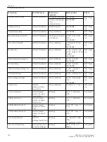


voltage 3 · V
0
can be calculated by the device based on the three phase–to–ground voltages. In the latter case,
the three voltage inputs must be connected to voltage transformers in a grounded-wye configuration (see also
address 213
VT Connect. 3ph
). If the device is only provided
with phase-to-phase voltages, it is not possible to calculate a displacement voltage from them. In this case the
direction cannot be determined.
If the displacement voltage is calculated, then:
3 · V
0
= V
A
+ V
B
+ V
C
If the displacement voltage is directly applied to the device, then V
0
is the voltage at the device terminals. It is
not affected by parameter
Vph / Vdelta
(address 206).
Pickup performed by the displacement voltage can be delayed (
64-1 DELAY
) for tripping.
It is important to note that the total trip-command time then consists of the displacement voltage measure-
ment time (about 50 ms) plus the pickup delay time
64-1 DELAY
.
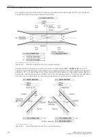
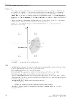
After the voltage element picks up due to detection of a displacement voltage, the grounded phase is identi-
fied, if possible. To do this, the individual phase-to-ground voltages are measured. Of course, this is only
possible if three phase-to-ground voltages are obtained from voltage transformers connected in a grounded
wye configuration. If the voltage magnitude for any given phase is below the setting value V
Ph min
, that phase
is detected as the grounded phase as long as the remaining phase-to-ground voltages are simultaneously
above the setting value V
Ph max
.
[7sj6x_erdschlussbehaftete_phase-150502-kn, 1, en_US]
Figure 2-87
Determination of Ground-faulted Phase
Current Elements
There are two current elements. Both elements operate directionally, whereby the tripping zones can be set
individually for each element (see margin heading “Tripping Area”). Both current elements are provided with a
definite time characteristic. Two current/time elements are used for ground fault protection. Analog to the
time overcurrent protection function, the overcurrent element is named
50Ns-1 PICKUP
and
50Ns-1
DELAY
and the high-set element
50Ns-2 PICKUP
and
50Ns-2 DELAY
.
The pickup of the definite time overcurrent protection can be stabilized by the configured dropout delay time
(address 3121
50Ns T DROP-OUT
).
Functions
2.13 Ground Fault Protection 64, 67N(s), 50N(s), 51N(s)
SIPROTEC 4, 7SJ62/64, Manual
207
C53000-G1140-C207-8, Edition 08.2016
Summary of Contents for SIPROTEC 4
Page 8: ...8 SIPROTEC 4 7SJ62 64 Manual C53000 G1140 C207 8 Edition 08 2016 ...
Page 18: ...18 SIPROTEC 4 7SJ62 64 Manual C53000 G1140 C207 8 Edition 08 2016 ...
Page 30: ...30 SIPROTEC 4 7SJ62 64 Manual C53000 G1140 C207 8 Edition 08 2016 ...
Page 540: ...540 SIPROTEC 4 7SJ62 64 Manual C53000 G1140 C207 8 Edition 08 2016 ...
Page 594: ...594 SIPROTEC 4 7SJ62 64 Manual C53000 G1140 C207 8 Edition 08 2016 ...
Page 720: ...720 SIPROTEC 4 7SJ62 64 Manual C53000 G1140 C207 8 Edition 08 2016 ...


