[7sj62-64-ffm-messspag-ausfall-20120611, 2, en_US]
Figure 2-74
Logic diagram of the Fuse Failure Monitor for isolated and grounded systems
Single- and Two-phase Failures in Voltage Transformer Circuits
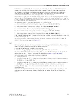
The measuring voltage failure detection is based on the fact that a significant negative sequence system is
formed in the voltage during single- or two-phase voltage failure, however without influencing the current.
This enables a clear distinction from asymmetries impressed by the power system. If the negative sequence
system is related to the current positive sequence system, the following rules apply to the Fault-free Case:
[u2-u1-fehlerfreier-fall-020828-ho, 1, en_US]
If a fault occurs in the voltage transformer secondary system, the following rules apply to the Single-phase
Failure:
Functions
2.12 Monitoring Functions
188
SIPROTEC 4, 7SJ62/64, Manual
C53000-G1140-C207-8, Edition 08.2016
Summary of Contents for SIPROTEC 4
Page 8: ...8 SIPROTEC 4 7SJ62 64 Manual C53000 G1140 C207 8 Edition 08 2016 ...
Page 18: ...18 SIPROTEC 4 7SJ62 64 Manual C53000 G1140 C207 8 Edition 08 2016 ...
Page 30: ...30 SIPROTEC 4 7SJ62 64 Manual C53000 G1140 C207 8 Edition 08 2016 ...
Page 540: ...540 SIPROTEC 4 7SJ62 64 Manual C53000 G1140 C207 8 Edition 08 2016 ...
Page 594: ...594 SIPROTEC 4 7SJ62 64 Manual C53000 G1140 C207 8 Edition 08 2016 ...
Page 720: ...720 SIPROTEC 4 7SJ62 64 Manual C53000 G1140 C207 8 Edition 08 2016 ...


