Programming and Operating Manual (Milling)
6FC5398-4DP10-0BA1, 01/2014
151
Explanation of the parameters
For the parameters RTP, RFP, SDIS, DP, DPR, refer to Section "Drilling, centering - CYCLE81 (Page 126)".
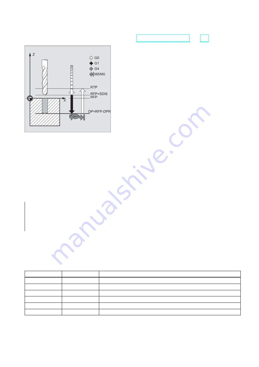
DTB (dwell time)
The dwell time to the final drilling depth (chip breakage) is programmed under DTB in seconds.
SDIR (direction of rotation)
The programmed direction of rotation is active for the distance to be traversed to the final drilling depth.
If values other than 3 or 4 (M3/M4) are generated, alarm 61102 "No spindle direction programmed" is generated and the
cycle is aborted.
Programming example: Fourth drilling
CYCLE88 is called at position X80 Y90 in the XY plane. The drilling axis is the Z axis. The safety clearance is programmed
with 3 mm; the final drilling depth is specified relative to the reference plane.
M4 is active in the cycle.
N10 G17 G90 F100 S450
; Specification of technology values
N20 G0 X80 Y90 Z105
; Approach drilling position
N30 CYCLE88 (105, 102, 3, , 72, 3, 4)
; Cycle call with programmed spindle
direction M4
N40 M02
; End of program
9.4.12
Reaming 2 - CYCLE89
Programming
CYCLE89 (RTP, RFP, SDIS, DP, DPR, DTB)
Parameters
Parameter
Data type
Description
RTP
REAL
Retraction plane (absolute)
RFP
REAL
Reference plane (absolute)
SDIS
REAL
Safety clearance (enter without sign)
DP
REAL
Final drilling depth (absolute)
DPR
REAL
Final drilling depth relative to the reference plane (enter without sign)
DTB
REAL
Dwell time at final drilling depth (chip breakage)


