Programming and Operating Manual (Milling)
6FC5398-4DP10-0BA1, 01/2014
245
Machine manufacturer
The names of the identifiers (X or Y ...) are defined in the machine data where they can also be changed.
Transition to next element
A transition element can be used whenever there is a point of intersection between two neighboring elements; this can be
calculated from the input values.
You can choose to insert either a radius (RND), a chamfer (CHR) or an undercut as the transition element between any two
contour elements. The transition is always appended to the end of a contour element. You select transition elements in the
parameter input screen for the relevant contour element.
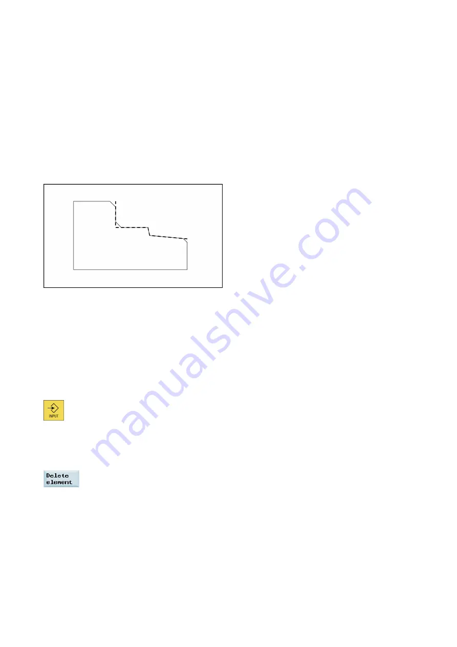
Radius or chamfer at the start or the end of a turning contour:
In simple turning contours a chamfer or radius must often be appended at the start and end of the contour.
A chamfer or radius terminates an axis-parallel contour section on the blank:
You select the direction of transition for the contour start in the starting point screen. You can choose between chamfer and
radius. The value is defined in the same manner as for the transition elements.
In addition, four directions can be selected in a single selection field. You select the direction of the transition element for the
contour end in the end screen. This selection is always proposed, even if preceding elements were assigned no transition.
Contour chain
Once you complete or cancel the programming of a contour element, you can navigate around the contour chain (left on the
main screen) using the cursor keys. The current position in the chain is color-highlighted.
The elements of the contour and pole, if applicable, are displayed in the sequence in which they were programmed.
You can select an existing contour element with the following key and reassign its parameters:
A new contour element is inserted after the cursor when you select one of the contour elements on the vertical softkey bar;
the input focus is then switched to the parameter input on the right of the graphic display. Programming always continues
after the element selected in the contour chain.
You can delete the selected element from the chain by selecting the following softkey:
Graphics window
The graphics window displays the progress of the contour chain as you configure the parameters for the contour elements.
The element you have selected is displayed in black in the graphics window.
The contour is displayed to the extent it can be interpreted by the control on the basis of parameter inputs. If the contour is
still not displayed in the programming graphic, further values must be entered. Check the contour elements you have already
programmed, if required. You may have forgotten to enter all of the known data.
The coordinate system scaling is automatically adapted to changes in the complete contour.


