Programming and Operating Manual (Milling)
226
6FC5398-4DP10-0BA1, 01/2014
Operating sequence
1.
Select the desired operating area.
2.
Open the list of user data.
3.
Use the cursor keys to navigate in the list, and enter the values in the input fields to be modified.
Note:
You can search for your desired user data with the following softkey.
You can press the following softkey to continue searching your desired user data.
4.
Use this key or move the cursor to confirm your entries.
A.8
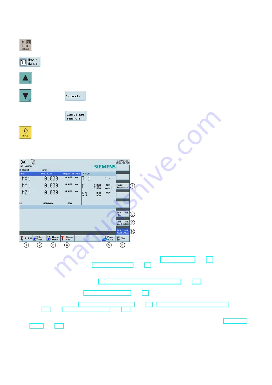
Other settings in "JOG" mode
①
Opens the "T, S, M" window where you can activate tools (see Section "Activating the tool (Page 20)"), set spindle
speed and direction (see Section "Activating the spindle (Page 22)"), and select a G code or other M functions for
activating the settable work offset.
②
Switches the display to the relative coordinate system. You can set the reference point in this coordinate system. For
detailed information, refer to Section "Setting the relative coordinate system (REL) (Page 227)".
③
Opens the workpiece measurement window where you determine the work offset data. For detailed information about
this window, refer to Section "Setting up the workpiece (Page 25)".
④
Opens the tool measurement window where you determine the tool offset data. For detailed information about this
window, refer to Sections "Measuring the tool (manually) (Page 23)", "Measuring the tool with a probe (auto)
(Page 220)" and "Calibrating the tool probe (Page 219)".
⑤
Opens the face cutting window where you specify parameters for machining the end face or peripheral surface of a
blank without creating a special part program. For detailed information about this window, refer to Section "Face
⑥
Opens the settings window where you can set JOG feedrate and variable increment values.


