Technical Appendix
6.3
PLC user program for turning (UPGMTURN)
6-147
SINUMERIK 802S
6FC5 597–2AA00–0BP2 (01.02)
Description of the input signals
S
UPGMTURN supports only toolholders with a separate output for each position, i.e. abso-
lute encoders are not supported. I0.0 to I0.5 are linked with the toolholder. When using
versions with only 4 locations, the inputs I0.4, I0.5 must be marked as invalid inputs.
S
With toolholders providing a “Toolholder clamped” signal, this signal should be connected
to I0.6; otherwise, I0.6 will be marked invalid.
S
Each axis of the system requires hardware limit switches for both directions (+/-). The limit
switch signals are monitored from the NCK in all operating modes. In the event a limit
switch is overrun, all axes are stopped, and only the axis resulted in responding of the limit
switch can be traversed to the opposite direction in JOG mode.
S
Referencing (delayed reference-point approach) requires a cam switch on the inputs I1.4
for the X axis and I1.5 for the Z axis. In addition, a reference-point switch (BERO) must be
connected to the NCK input (X20) to ensure that the reference point is set exactly (see
Start–up Guide).
S
The drive ready signal is connected to input I1.6. As long as the signal is logic “0”, alarm
700003 is output.
S
The alarm input can be used for alarm signals from the machine tool, e.g. for temperature
monitoring relays or the like. The effect is the same as with EMERGENCY STOP - all axes
and the spindle are stopped.
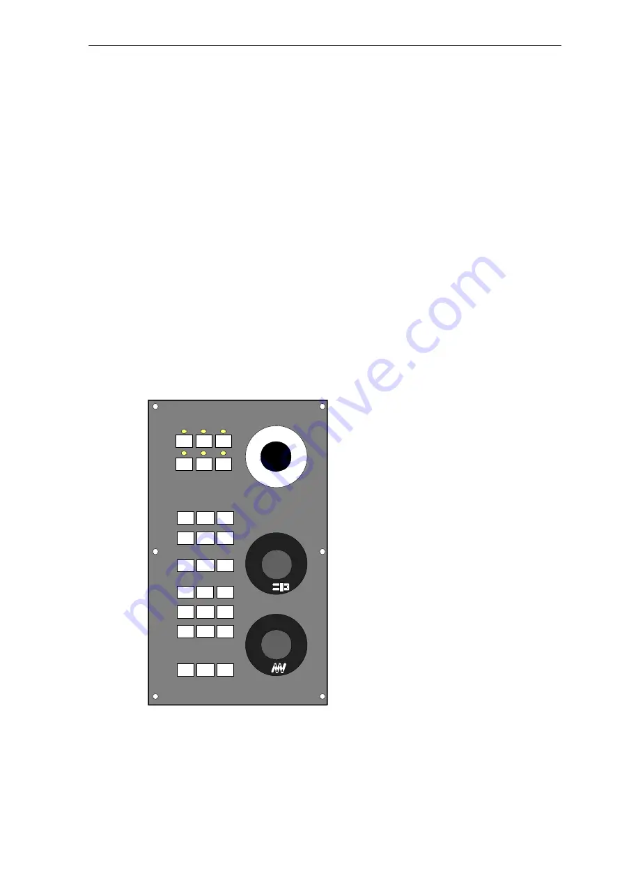
UPGMTURN function keys on the machine control panel
%
%
#1
#2
#3
#4
#5
#6
#16
#18
#22
#24
Fig. 6-1
Keyboard layout
S
#1: Reduce spindle speed <<
Summary of Contents for SINUMERIK 802S
Page 1: ...Start Up 01 2002 Edition SINUMERIK 802S ...
Page 2: ......
Page 8: ...Table of Contents viii SINUMERIK 802S 6FC5 597 2AA00 0BP2 01 02 notice ...
Page 104: ...Start Up 4 7 Commissioning 4 104 SINUMERIK 802S 6FC5 597 2AA00 0BP2 01 02 ...
Page 170: ...Index Index 170 SINUMERIK 802S 6FC5 597 2AA00 0BP2 01 02 notice ...
Page 172: ......


