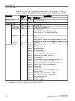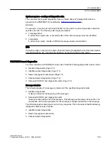
The diagnostic data type can be uniquely identified based on the header.
Note
The master must operate in the DPV1 mode.
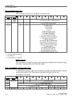
Standard diagnostics
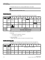
For communication via PROFIBUS, standard diagnostics is structured as follows.
Bit
7
6
5
4
3
2
1
0
Octet
Name
1
Station
status 1
Master_
Lock
= 0
Prm_Fault
0
Not_
Supported
Ext_Diag
Cfg_Fault
Station_
Not_
Ready
Station_
Non_
Exist
= 0
2
Station
status 2
0
0
Sync_
Mode
Freeze_
Mode
WD_On
1
Stat_Diag
= 0
Prm_Req
3
Station
status 3
Ext_
Diag_
Overflow
0
0
0
0
0
0
0
4
Master_Add
5
Ident_Number (HighByte) of the slave
6
Ident_Number (LowByte) of the slave
In this context, the following values are decisive for diagnostics:
● Ext_Diag
– Group signal for diagnostics in the slave
– = 1, if at least 1 alarm is active
● Ext_Diag_Overflow
Display, diagnostics overflow in the slave (for more than 240 bytes)
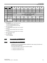
Identifier-related diagnostics
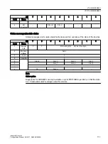
The identifier-related diagnostics provides a bit (KB_n) for each slot 1 allocated when
configuring the device. If a diagnostics message is active at a slot, then it's KB_n = true.
Bit
7
6
5
4
3
2
1
0
Octet
Name
1
Header-
Byte
Station
status 1
0
1
Block length (2 ... 32) incl. this byte
2
Bit
structure
KB_7
KB_6
KB_5
KB_4
KB_3
KB_2
KB_1
KB_0
3
Bit
structure
...
...
...
...
KB_11
KB_10
KB_9
KB_8
Communication
A.1 Communication
Industrial Security
110
Configuration Manual, 08/2017, A5E36912609A


