


A.1.6.2
Topology
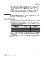
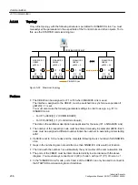
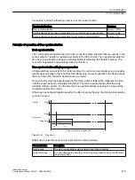
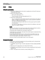
Only a line topology with the following structure is permitted for SINAMICS Link. You must
manually set the parameters in the expert lists of the Control Units and drive objects. To do
this, use the STARTER commissioning tool.
352),%86352),1(7
6,1$0,&6/LQN
3
3
6,1$0,&6
&%(
S
3
3
3
3
6,1$0,&6
&%(
S
3
3
3
3
6,1$0,&6
&%(
S
3
3
3
3
6,1$0,&6
&%(
S
3
3
Figure A-39 Maximum topology
Features
● The CBE20 can be assigned to IF1 or IF2 when SINAMICS Link is used.
The interface, assigned to the CBE20, must be switched into synchronous operation if
p8812[0] = 1 is set.
You must also make the following parameter settings in order to assign, e.g. IF1 to
SINAMICS Link:
– For IF1: p8839[0] = 2 (COMM BOARD)
– For IF2: p8839[1] = 1 (Control Unit onboard)
The data in the additional description are applicable for the case (IF1 ≙ SINAMICS Link).
● The number of the respective node must be entered manually in parameter p8836. Each
node must be assigned a different number. Enter the numbers in ascending order starting
with 1.
● If p8836 is set to 0, the nodes and the complete following line is shut down for SINAMICS
Link.
● Gaps in the numbering are not permitted, as then SINAMICS Link would not function.
● The node with the number 1 is automatically the sync master of the communication link.
● The ports of the CBE20 must be interconnected strictly in accordance with the above
diagram. You must always connect port 2 (P2) of node n with port 1 (P1) of node n + 1.
● In the "SINAMICS Link" mode, ports 3 and 4 of the CBE20 can only be used to connect to
the STARTER commissioning tool or Startdrive.
Communication
A.1 Communication
Industrial Security
206
Configuration Manual, 08/2017, A5E36912609A


