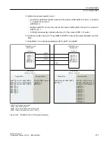
5. Set all CBE20 to the isochronous mode by setting p8812[0] = 1.
6. Make the following interface setting for all nodes:
– For IF1: p8839[0] = 2 (COMM BOARD)
– For IF2: p8839[1] = 1 (Control Unit onboard)
7. For both nodes p0009 = 0, carry out a "Copy RAM to ROM" followed by a POWER ON in
order to activate the modified firmware versions and the new settings in the CBE20.
8. Define the send data for node 1:
– Define the PZD that node 1 should send:
p2051[0] = drive 1:r0898 (PZD 1)
p2061[1] = drive1:r0079 (PZD 2 + PZD 3)
p2061[3] = drive1:r0021 (PZD 4 + PZD 5)
– Place these PZD in the send buffer (p8871) of node 1:
p8871[0] = 1 (r0898)
p8871[1] = 2 (r0079 1st part)
p8871[2] = 3 (r0079 2nd part)
p8871[3] = 4 (r0021 1st part)
p8871[4] = 5 (r0021 2nd part)
9. Define the receive data for node 2:
– Specify that the data placed in the receive buffer p8872 of node 2 in locations 0 to 4 will
be received by node 1:
p8872[0] = 1
p8872[1] = 1
p8872[2] = 1
p8872[3] = 1
p8872[4] = 1
– Specify that PZD1, PZD2, and PZD3 of node 1 will be placed in the receive buffer p8870
of node 2 in locations 0 to 4:
p8870[0] = 1 (PZD1)
p8870[1] = 2 (PZD2 1st part)
p8870[2] = 3 (PZD2 2nd part)
p8870[3] = 4 (PZD3 1st part)
p8870[4] = 5 (PZD3 2nd part)
– r2050[0], r2060[1] and r2060[3] subsequently contain (after step 13) the values of PZD 1,
PZD 2 and PZD 3 of node 1.
10.Define the send data for node 2:
– Specify the PZD that node 2 should send:
:p2051[0] = drive1:r0899 (PZD length is 1 word)
– Place this PZD in the send buffer (p8871) of node 2:
p8871[0] = 1
Communication
A.1 Communication
Industrial Security
212
Configuration Manual, 08/2017, A5E36912609A

