


Modbus TCP always provides a basic Ethernet functionality, which corresponds to the
functionality of Ethernet interface X127:
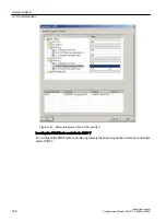
● Commissioning access for STARTER/Startdrive with S7 protocol
● DCP to set the IP address etc.
● SNMP for identification
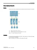
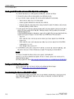
General information about communication
Communication with Modbus TCP runs via the Ethernet/PROFINET interfaces:
● X150:
For Modbus TCP with a CU320-2 PN.
● X1400:
For Modbus TCP with a CU320-2 PN or a CU320-2 DP via a CBE20.
Precisely one Modbus connection can be established. Simultaneous connection via the
interfaces X150 and X1400 is not possible and is acknowledged with alarm A08555(1).
However, you can use one interface for Modbus TCP, and the other as PROFINET interface.
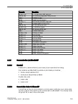
Drive object that can be addressed via Modbus
With Modbus TCP, you always address the first drive object from the list of drive objects
(p0978[0]). A servo or vector drive object must be in this parameter.
● However, Modbus TCP is only activated if, under p0978[0], there is a drive object that is
supported by Modbus TCP.
● If p0978[0] does not contain a valid drive object, then establishing communication is
acknowledged with alarm A08555(2).
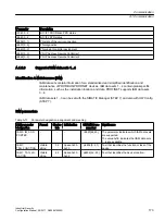
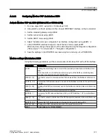
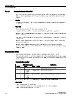
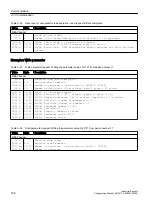
Diagnostics LEDs in Modbus TCP
Diagnostics states are shown as follows using LEDs with Modbus TCP:
● X150: "PN" LED
● X1400 (CBE20): "OPT" LED
The following states can be displayed by these LEDs:
Color
State
Significance
Green
Continuous
light
Connections and setpoints are OK.
Green
Flashing light
Connection is OK, but no setpoints (dependent on timeout).
Red
Flashing light
2 Hz
No connection or setpoint timeout.
Communication
A.1 Communication
Industrial Security
176
Configuration Manual, 08/2017, A5E36912609A


