


● PROFIBUS interface
The PROFIBUS interface is described on the CD of the converter in the document
"Supplementary component descriptions".
● PROFIBUS diagnostic LED
Note
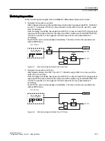
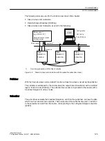
A teleservice adapter can be connected to the PROFIBUS interface (X126) for remote
diagnostics purposes.
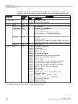
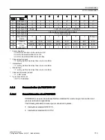
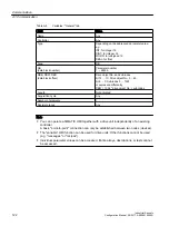
PROFIBUS address switch
On the CU320-2 DP, the PROFIBUS address is set as a hexadecimal value via two rotary
coding switches. Values between 0
dec
(00
hex
) and 127
dec
(7F
hex
) can be set as the address. The
upper rotary coding switch (H) is used to set the hexadecimal value for 16
1
and the lower rotary
coding switch (L) is used to set the hexadecimal value for 16
0
.
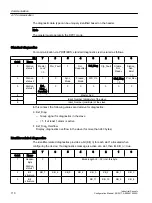
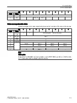
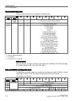
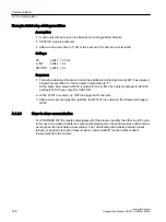
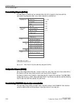
Table A-6
PROFIBUS address switch
Rotary coding switches
Significance
Examples
21
dec
35
dec
126
dec
15
hex
23
hex
7E
hex
C
D
E
A
B
F
DP
H
1
0
2
3
4
5
6
78
9
16
1
= 16
1
2
7
C
D
E
A
B
F
DP
L
1
0
2
3
4
5
6
78
9
16
0
= 1
5
3
E
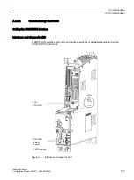
Setting the PROFIBUS address
The factory setting for the rotary coding switches is 0
dec
(00
hex
).
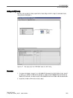
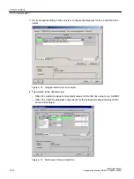
There are two ways to set the PROFIBUS address:
1. Using a parameter
– To set the bus address for a PROFIBUS node using STARTER, first set the rotary code
switches to 0
dec
(00
hex
) and/or 127
dec
(7F
hex
).
– Use the parameter to set the address to a value between 1 and 126.
For further information, please refer to the converter List Manual.
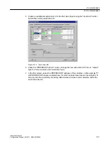
2. Using the PROFIBUS address switches on the Control Unit
– The address is set manually to values between 1 and 126 using the rotary coding
switches. In this case, the parameter is only used to read the address.
Communication
A.1 Communication
Industrial Security
118
Configuration Manual, 08/2017, A5E36912609A


