Installation
4.3 Connecting the inverter to PROFINET
Converter with the control units CU240D-2
74
Operating Instructions, 04/2018, FW V4.9 SP10, A5E34262100B AF
Further information on the operation as Ethernet nodes can be found in the Function Manual
"Fieldbuses".
Overview of the manuals (Page 343)
Further information on PROFINET
Further information on PROFINET can be found on the Internet:
●
PROFINET – the Ethernet standard for automation
http://w3.siemens.com/mcms/automation/en/industrial-
communications/profinet/Pages/Default.aspx
●
PROFINET system description
https://support.industry.siemens.com/cs/ww/en/view/19292127
4.3.1
Connecting the PROFINET interface
Industrial Ethernet Cables and cable length
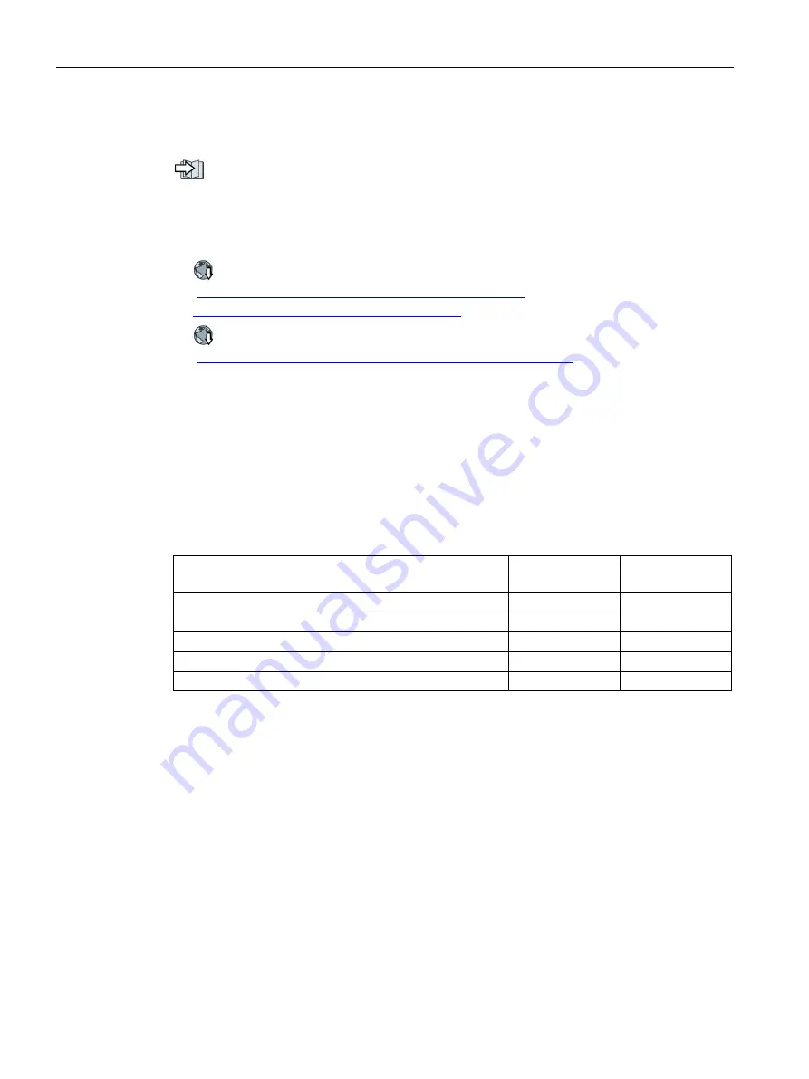
Listed in the table below are the recommended Ethernet cables.
Table 4- 16 Recommended PROFINET cables
Cable type
Max. length be-
tween devices
Article Number
Industrial Ethernet FC TP Standard Cable GP 2 x 2
100 m (328 ft)
6XV1840-2AH10
Industrial Ethernet FC TP Flexible Cable GP 2 x 2
85 m (278 ft)
6XV1870–2B
Industrial Ethernet FC Trailing Cable GP 2 x 2
85 m (278 ft)
6XV1870–2D
Industrial Ethernet FC Trailing Cable 2 x 2
85 m (278 ft)
6XV1840–3AH10
Industrial Ethernet FC Marine Cable 2 x 2
85 m (278 ft)
6XV1840–4AH10
Cable screening
The screen of the PROFINET cable must be connected with the protective earth. The solid
copper core must not be scored when the insulation is removed from the core ends.
4.3.2
What do you have to set for communication via PROFINET?
Configuring PROFINET communication in the I/O controller
You require the appropriate engineering system to configure PROFINET communication in
the IO controller.
If required, load the GSDML file of the inverter into the engineering system.


