Commissioning
5.5 Quick commissioning with a PC
Converter with the control units CU240D-2
94
Operating Instructions, 04/2018, FW V4.9 SP10, A5E34262100B AF
Selecting the control mode (Page 87)
Select the I/O configuration to preassign the inverter interfaces.
Default settings of inputs and outputs (Page 63)
Set the applicable motor standard and the inverter supply voltage.
Select the application for the inverter:
●
"[0] Load cycle with high overload for applications requiring a high dynamic performance,
e.g. conveyor systems.
●
"[1] Load cycle with low overload ..." for applications that do not require a high dynamic
performance, e.g. pumps or fans.
●
[6], [7]: Load cycles for applications with encoderless 1FK7 synchronous motors.
If an optional component is installed between inverter and motor, the corresponding setting
must be performed.
Select your motor.
Enter the motor data according to the rating plate of your motor.
If you have selected a motor based on its article number, the data has already been entered.
Select the temperature sensor for monitoring of the motor temperature.
Define whether the inverter actuates a motor holding brake.
Set the most important parameters to suit your application.
Select the technological application:
●
[0]: In all applications that do not fall under [2]
●
[2]: Encoderless control down to standstill
Motor identification:
●
[2]: Measure the motor data at standstill. The inverter switches off the motor after the
motor data identification has been completed.
Calculating the motor parameters: Select "Complete calculation".
If you use an HTL encoder on the motor shaft for the speed control of the inverter, either
select one of the standard encoders or enter the encoder data.
…R: Encoder with zero mark
Adapting the encoder data (Page 95)
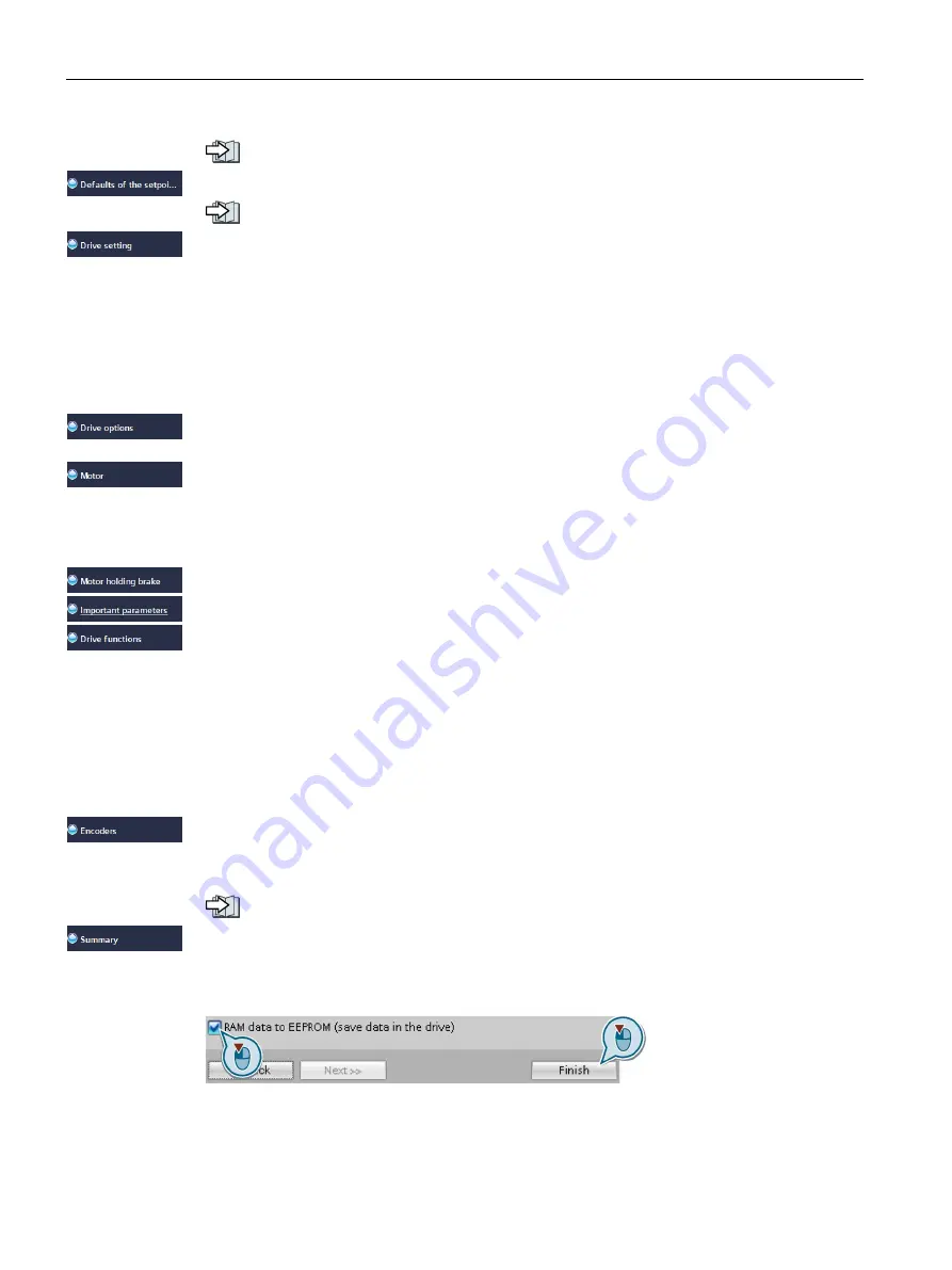
Set the check mark for "RAM data to EEPROM (save data in the drive)" to save your data in
the inverter so that it is not lost if the power fails.
Press the "Finish" button.


