


7SR11 & 7SR12 Commissioning and Maintenance Guide
©2017 Siemens Protection Devices Limited
Chapter 6 Page 52 of 72
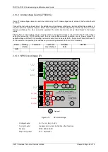
2.15
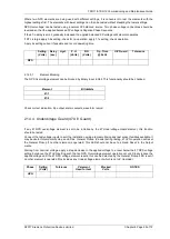
Under/Over Frequency (81)
7SR12
46
BC
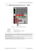
46
NPS
(x2)
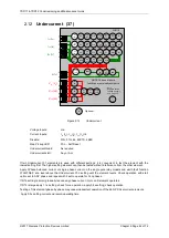
37
(x2)
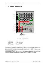
49
50
BF
51V
V
L1
(V
A
)
V
L2
(V
B
)
V
L3
(V
C
)
I
L1
(I
A
)
81
HBL
2
37
(x2)
49
50
BF
51V
I
L2
(I
B
)
81
HBL
2
37
(x2)
49
50
BF
51V
I
L3
(I
C
)
81
HBL
2
I
4
(I
G
)
74
T/
CCS
NOTE: The use of some
functions are mutually exclusive
67/
50
(x4)
67/
51
(x4)
67/
50N
(x4)
67/
50
(x4)
67/
50
(x4)
67/
51
(x4)
67/
51
(x4)
67/
51N
(x4)
67/
50
SEF
67/
51
SEF
27
59
(x4)
27
59
(x4)
27
59
(x4)
47
(x2)
79
Optional
59N
(x2)
Note:
Example shows
Voltage Config =
Van, Vbn, Vcn
60
CTS
60
VTS
50BF
51c
51c
51c
64H
81
(x4)
Figure 2-18
Under/Over Frequency
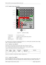
Voltage Inputs:
V
L1
(V
A
), V
L2
(V
B
), V
L3
(V
C
)
Current Inputs:
n/a apply zero current to stabilize other functions
Disable:
Map Pickup LED:
81-n - Self Reset
This function can be tested by application of 1P or 3P voltage. For Over-frequency, the elements with the highest
setting should be tested first and for Under-frequency the elements with the lowest settings should be tested first.
The elements with other settings can then be tested without need to disable the elements already tested. Note
that the relay is designed to track the gradual changes in power system frequency and that sudden step changes
in frequency during testing do not reflect normal system operation. Normal ‘instantaneous’ operation of the
frequency element is 140-175ms in line with the Performance Specification. Application of sudden step changes
to frequency can add additional delay which can produce misleading test results.
Gradually increase/decrease applied voltage frequency until 81-n operation occurs. Elements set for more
extreme frequency fluctuation should be tested first with lesser elements disabled.
If the 81-n Delay setting is long it will be advantageous to map the function to temporarily drive the relevant
Pickup output in the
Pickup Config
sub-menu in the
Output Config
menu as this will allow the Pick-up led to
operate for the function. If the delay setting is short the operation of the element can be easily checked directly.
The frequency should then be gradually decreased/increased until the element resets. The reset frequency can
be used to check the Hysteresis setting.
If the element is set as
81-n U/V Guarded
, The applied voltage must be above the
81 UV Guard Setting
in the
U/O Frequency
menu.
Apply setting fre0.5Hz for Over-frequency or -0.5Hz for Under-frequency and record operating time.
Starting with the element in the operated condition, gradually increase or decrease the applied voltage until the
element resets. Measure the reset voltage level to check the
81 Hysteresis
setting.
Summary of Contents for Argus 7SR11
Page 1: ...Energy Management 7SR11 7SR12 Argus Overcurrent Relay Reyrolle Protection Devices ...
Page 2: ......
Page 4: ...7SR11 7SR12 Argus Contents 2015 Siemens Protection Devices Limited Page 2 of 2 ...
Page 170: ...7SR120 Technical Manual Chapter 4 Page 2 of 84 2017 Siemens Protection Devices Limited ...
Page 174: ...7SR120 Technical Manual Chapter 4 Page 6 of 84 2017 Siemens Protection Devices Limited ...
Page 196: ...7SR120 Technical Manual Chapter 4 Page 28 of 84 2017 Siemens Protection Devices Limited ...
Page 242: ...7SR120 Technical Manual Chapter 4 Page 74 of 84 2017 Siemens Protection Devices Limited ...
Page 244: ...7SR120 Technical Manual Chapter 4 Page 76 of 84 2017 Siemens Protection Devices Limited ...
Page 246: ...7SR120 Technical Manual Chapter 4 Page 78 of 84 2017 Siemens Protection Devices Limited ...
Page 254: ...7SR11 7SR12 Installation Guide Chapter 5 Page 2 of 32 2017 Siemens Protection Devices Limited ...
Page 358: ...7SR11 7SR12 Applications Guide Page 2 of 48 2017 Siemens Protection Devices Limited ...
Page 405: ......


