


7SR11 & 7SR12 Commissioning and Maintenance Guide
©2017 Siemens Protection Devices Limited
Chapter 6 Page 47 of 72
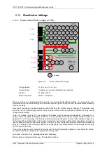
Where more than one overvoltage (59) elements are being used with different settings, it is convenient to test the
elements with the highest settings first. The elements with lower settings can then be tested without disabling the
higher settings.
If the ‘O/P Phases’ is set to ‘All’, the voltage on all phases must be increased simultaneously. Otherwise the 3
phases should be tested individually. If the DTL setting is short, starting from nominal voltage, slowly increase the
applied 3P or VL1 test voltage until the Pickup LED (temporarily mapped) is lit. The LED should light at setting
Volts +/-5% Decrease the input voltage to nominal Volts and the LED will extinguish. Record the reset voltage to
check the ‘Hysteresis’ setting. If the DTL setting is long, the operate level can be checked by applying 100% of
setting to cause operation followed by setting minus the Hysteresis setting to cause reset.
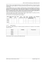
Connect the relevant output contact(s) to stop the test set. Step the applied voltage to a level above the setting.
The test set should be stopped at the operate time s/-5%
Test inputs VL2 and VL3 by repeating the above if necessary.
Phase Setting
(Volts)
U/O
DTL
(sec)
Hyst.
D.O.
(calculated)
P.U.
Volts
D.O
Volts
Op. Time
@ 2x Vs (OV)
@ 0.5x Vs (UV)
UV
Guard
Tolerance
V
1
(V
A
)
V
2
(V
B
)
V
3
(V
C
)
2.14.1.1
Element Blocking
The Under/Over Voltage elements can be blocked by Binary Input Inhibit and VT Supervision. This functionality
should be checked.
Element
BI Inhibits
VT Supervision
27/59-1
27/59-2
27/59-3
27/59-4
When testing is complete reinstate any of the disabled functions.
Summary of Contents for Argus 7SR11
Page 1: ...Energy Management 7SR11 7SR12 Argus Overcurrent Relay Reyrolle Protection Devices ...
Page 2: ......
Page 4: ...7SR11 7SR12 Argus Contents 2015 Siemens Protection Devices Limited Page 2 of 2 ...
Page 170: ...7SR120 Technical Manual Chapter 4 Page 2 of 84 2017 Siemens Protection Devices Limited ...
Page 174: ...7SR120 Technical Manual Chapter 4 Page 6 of 84 2017 Siemens Protection Devices Limited ...
Page 196: ...7SR120 Technical Manual Chapter 4 Page 28 of 84 2017 Siemens Protection Devices Limited ...
Page 242: ...7SR120 Technical Manual Chapter 4 Page 74 of 84 2017 Siemens Protection Devices Limited ...
Page 244: ...7SR120 Technical Manual Chapter 4 Page 76 of 84 2017 Siemens Protection Devices Limited ...
Page 246: ...7SR120 Technical Manual Chapter 4 Page 78 of 84 2017 Siemens Protection Devices Limited ...
Page 254: ...7SR11 7SR12 Installation Guide Chapter 5 Page 2 of 32 2017 Siemens Protection Devices Limited ...
Page 358: ...7SR11 7SR12 Applications Guide Page 2 of 48 2017 Siemens Protection Devices Limited ...
Page 405: ......