


7SR11 & 7SR12 Commissioning and Maintenance Guide
©2017 Siemens Protection Devices Limited
Chapter 6 Page 35 of 72
During testing of the
67SEF Ires select
residual current setting it is essential that the wattmetric power
setting is also exceeded. This can usually be achieved by applying the test current to the SEF input
whilst applying a nominal single phase voltage, in anti-phase with the current, to all 3 phase to neutral
voltage inputs. In this way, the wattmetric power is equal to the product of 3 times the applied voltage
and the applied current and this should always be greater than the Wattmetric power setting.
2.9.4
Inverse Time Overcurrent (51SEF)
It will be advantageous to map the function being tested to temporarily drive the relevant Pickup output in the
Pickup Config
sub-menu in the
Output Config
menu as this will allow the Pick-up led to operate for the function.
Gradually increase current until Pickup LED operates.
Apply 2x setting current and record operating time,
Apply 5x setting current and record operating time.
Compare to calculated values for operating times
P.U.
D.O.
&
TIMING
TESTS
Ph.
Dir
Char.
(NI EI VI LTI,
DTL)
Is
(A)
TM
Operate Current
Operate Time
P.U.
(Amps)
D.O.
(Amps)
Tol
2 x Is
(sec)
5 x Is
(sec)
Tol
I
4
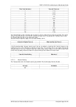
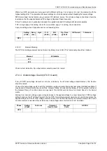
Calculated Timing values in seconds for TM =1.0
Curve
2 xIs
5 xIs
IEC-NI
10.03
4.28
IEC-VI
13.50
3.38
IEC-EI
26.67
3.33
IEC-LTI
120.00
30.00
ANSI-MI
3.80
1.69
ANSI-VI
7.03
1.31
ANSI-EI
9.52
1.30
Note that the operate time may be subject to the
Minimum op time
setting for the element and/or may have a
Follower DTL
applied.
If VTS action is set to BLOCK, this option should be tested. Apply balanced voltage and current. Reduce a-phase
voltage to cause a VTS condition. Increase a-phase current and check that the element does not operate.
If VTS action is set to Non-Directional, this option should be tested. Apply balanced voltage and current. Reduce
a-phase voltage to cause a VTS condition. Increase a-phase current and check that the element operates at its
normal setting. Reverse the voltage phase direction whilst checking that the element does not reset.
2.9.4.1
Element Blocking
The Sensitive Earth Fault elements can be blocked by Binary Input Inhibit, VT Supervision and Wattmetric
protection. The Characteristic can be made non-directional by VT Supervision. This functionality should be
checked.
Element
BI Inhibits
VTS action
51SEF-1
51SEF-2
51SEF-3
51SEF-4
50SEF-1
50SEF-2
Summary of Contents for Argus 7SR11
Page 1: ...Energy Management 7SR11 7SR12 Argus Overcurrent Relay Reyrolle Protection Devices ...
Page 2: ......
Page 4: ...7SR11 7SR12 Argus Contents 2015 Siemens Protection Devices Limited Page 2 of 2 ...
Page 170: ...7SR120 Technical Manual Chapter 4 Page 2 of 84 2017 Siemens Protection Devices Limited ...
Page 174: ...7SR120 Technical Manual Chapter 4 Page 6 of 84 2017 Siemens Protection Devices Limited ...
Page 196: ...7SR120 Technical Manual Chapter 4 Page 28 of 84 2017 Siemens Protection Devices Limited ...
Page 242: ...7SR120 Technical Manual Chapter 4 Page 74 of 84 2017 Siemens Protection Devices Limited ...
Page 244: ...7SR120 Technical Manual Chapter 4 Page 76 of 84 2017 Siemens Protection Devices Limited ...
Page 246: ...7SR120 Technical Manual Chapter 4 Page 78 of 84 2017 Siemens Protection Devices Limited ...
Page 254: ...7SR11 7SR12 Installation Guide Chapter 5 Page 2 of 32 2017 Siemens Protection Devices Limited ...
Page 358: ...7SR11 7SR12 Applications Guide Page 2 of 48 2017 Siemens Protection Devices Limited ...
Page 405: ......