


7SR11 & 7SR12 Commissioning and Maintenance Guide
©2017 Siemens Protection Devices Limited
Chapter 6 Page 24 of 72
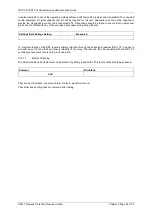
2.6
Directional Earth Fault Polarity Check (67N)
Derived Earth Fault, Measured Earth Fault and Sensitive Earth Fault elements can be set as directional. These
are polarised from residual voltage, calculated from the 3 phase voltage inputs or the 3Vo input depending on the
Phase Voltage Config
setting in the
CT/VT Config
menu.
The relay Char Angle setting is the Characteristic Phase angle of the fault impedance i.e. the phase angle of the
fault current with respect to the voltage driving the current. The earth fault functions are polarised from the
residual voltage which is in anti-phase with the fault voltage for a single-phase to earth fault. Care is required
when testing by secondary injection with regard to current and voltage polarity.
To simulate an earth fault on a relay with 3 phase-phase or 3 phase-neutral connected voltage inputs, defined by
the
Phase Voltage Config
setting of
Van,Vbn,Vcn
or
Va,Vb,Vc
, proceed as follows. Balanced 3P voltage should
first be applied, then the phase-neutral voltage magnitude on the faulted phase should be reduced in magnitude
with no change in phase angle to produce Vres and simulate the fault. The fault current, on the faulted phase
only, should be set at the MTA with respect to the phase-neutral voltage on the faulted phase, e.g. for a relay
setting of -15º, set the phase current to lag the ph-n voltage by 15º.
Alternatively, a single phase voltage source can be used in the above test. The polarity of this voltage, applied to
the faulted phase-neutral alone, must be reversed to produce the same residual voltage (Vres) phase direction as
that produced by the 3P voltage simulation described above.
For the
Phase Voltage Config
of
Vab, Vbc, Vo,
the single phase voltage applied to the Vo input is used as the
polarising quantity
.
The inversion is once again required since this input is designed to measure the residual
voltage directly, as produced by an ‘open delta VT’ arrangement. The current must be set at the MTA with respect
to the inversion of this voltage. e.g. for a relay setting of -15º, the phase current must lag the (Vo+180º) voltage by
15º, i.e. if Vo is set at 180º, set Iph at -15º.
If the Pickup of one directional Earth Fault element is mapped to an LED, this can be used to check directional
boundaries for pickup and drop-off as the current phase angle is increased and decreased. Note that the Derived
Earth Fault, Measured Earth Fault and Sensitive Earth Fault have separate directional settings and must be
tested individually.
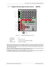
V
RES
The diagram opposite shows a Phase A –
Earth fault.
Apply residual voltage either directly to input or
by reducing voltage of faulted phase.
Adjust the phase angle of the phase current
relative to the voltage:
Verify directional pick-up and drop off at points
A, B, C and D
Alternatively,
Verify correct directional indication at points a,
b, c and d (C.A +75
0
, +95
0
, -75
0
, -95
0
)
A
B
D
C
a
d
b
c
FWD
REV
-30
0
-60
0
-90
0
180
0
+90
0
+120
0
+150
0
0
0
I
PHASE
I
A
I
B
I
C
C.A.
Figure 2-7
Directional Earth Fault Boundary System Angles
Summary of Contents for Argus 7SR11
Page 1: ...Energy Management 7SR11 7SR12 Argus Overcurrent Relay Reyrolle Protection Devices ...
Page 2: ......
Page 4: ...7SR11 7SR12 Argus Contents 2015 Siemens Protection Devices Limited Page 2 of 2 ...
Page 170: ...7SR120 Technical Manual Chapter 4 Page 2 of 84 2017 Siemens Protection Devices Limited ...
Page 174: ...7SR120 Technical Manual Chapter 4 Page 6 of 84 2017 Siemens Protection Devices Limited ...
Page 196: ...7SR120 Technical Manual Chapter 4 Page 28 of 84 2017 Siemens Protection Devices Limited ...
Page 242: ...7SR120 Technical Manual Chapter 4 Page 74 of 84 2017 Siemens Protection Devices Limited ...
Page 244: ...7SR120 Technical Manual Chapter 4 Page 76 of 84 2017 Siemens Protection Devices Limited ...
Page 246: ...7SR120 Technical Manual Chapter 4 Page 78 of 84 2017 Siemens Protection Devices Limited ...
Page 254: ...7SR11 7SR12 Installation Guide Chapter 5 Page 2 of 32 2017 Siemens Protection Devices Limited ...
Page 358: ...7SR11 7SR12 Applications Guide Page 2 of 48 2017 Siemens Protection Devices Limited ...
Page 405: ......


