


7SR11 & 7SR12 Commissioning and Maintenance Guide
©2017 Siemens Protection Devices Limited
Chapter 6 Page 33 of 72
2.9
Sensitive Earth fault (67/50S,67/51S)
7SR12
46
BC
46
NPS
(x2)
37
(x2)
49
50
BF
51V
V
L1
(V
A
)
V
L2
(V
B
)
V
L3
(V
C
)
I
L1
(I
A
)
81
HBL
2
37
(x2)
49
50
BF
51V
I
L2
(I
B
)
81
HBL
2
37
(x2)
49
50
BF
51V
I
L3
(I
C
)
81
HBL
2
I
4
(I
G
)
74
T/
CCS
NOTE: The use of some
functions are mutually exclusive
67/
50
(x4)
67/
51
(x4)
67/
50N
(x4)
67/
50
(x4)
67/
50
(x4)
67/
51
(x4)
67/
51
(x4)
67/
51N
(x4)
67/
50
SEF
67/
51
SEF
27
59
(x4)
27
59
(x4)
27
59
(x4)
79
Optional
Note:
Example shows
Voltage Config =
Van, Vbn, Vcn
60
CTS
60
VTS
50BF
51c
51c
51c
64H
47
(x2)
59N
(x2)
81
(x4)
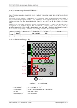
Figure 2-10
Sensitive Earth Fault
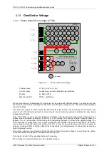
Voltage Inputs:
V
L1
(V
A
), V
L2
(V
B
), V
L3
(V
C
) for directional elements
Current Inputs:
I
4
(I
SEF
)
Disable:
64H, 50CBF, 79
Map Pickup LED:
51SEF-n/50SEF-n - Self Reset
Other protection functions may overlap with these functions during testing, it may be useful to disable some
functions to avoid ambiguity. Derived EF, Sensitive EF & Restricted EF protections can be Enabled/Disabled
individually or as groups in the ‘Function Config’ menu.
Sensitive EF elements can be separated from Derived EF by secondary injection of current through the I
4
input
circuit only.
If any of these elements are defined as directional the correct voltage phase direction will be required to produce
an operation of those elements.
The 67SEF elements will normally operate on the residual current through the I
4
input but can be set to operate
on only the real (wattmetric) component of this current by setting
67SEF Ires Select
to
Ires Real
. If this option is
selected, the residual current and voltage should be set in anti-phase during testing to so that the applied current
is purely real and can be measured directly.
If
67SEF Wattmetric
is set to
Enabled
, the residual real power must also exceed the
67SEF Wattmetric Power
setting to permit SEF operation
2.9.1
Directional Polarity
See section Directional Earth Fault Polarity Check above for testing details.
If
67SEF Wattmetric
is set to
Enabled
, the residual real power must also exceed the
67SEF Wattmetric Power
setting to permit SEF operation. As the directional boundary is approached, the Wattmetric current, will by
Summary of Contents for Argus 7SR11
Page 1: ...Energy Management 7SR11 7SR12 Argus Overcurrent Relay Reyrolle Protection Devices ...
Page 2: ......
Page 4: ...7SR11 7SR12 Argus Contents 2015 Siemens Protection Devices Limited Page 2 of 2 ...
Page 170: ...7SR120 Technical Manual Chapter 4 Page 2 of 84 2017 Siemens Protection Devices Limited ...
Page 174: ...7SR120 Technical Manual Chapter 4 Page 6 of 84 2017 Siemens Protection Devices Limited ...
Page 196: ...7SR120 Technical Manual Chapter 4 Page 28 of 84 2017 Siemens Protection Devices Limited ...
Page 242: ...7SR120 Technical Manual Chapter 4 Page 74 of 84 2017 Siemens Protection Devices Limited ...
Page 244: ...7SR120 Technical Manual Chapter 4 Page 76 of 84 2017 Siemens Protection Devices Limited ...
Page 246: ...7SR120 Technical Manual Chapter 4 Page 78 of 84 2017 Siemens Protection Devices Limited ...
Page 254: ...7SR11 7SR12 Installation Guide Chapter 5 Page 2 of 32 2017 Siemens Protection Devices Limited ...
Page 358: ...7SR11 7SR12 Applications Guide Page 2 of 48 2017 Siemens Protection Devices Limited ...
Page 405: ......


