


7SR11 & 7SR12 Commissioning and Maintenance Guide
©2017 Siemens Protection Devices Limited
Chapter 6 Page 48 of 72
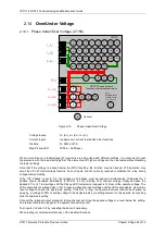
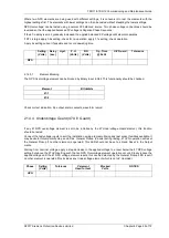
2.14.2 Undervoltage Guard (27/59UVG)
If any 27 Undervoltage element is set to be inhibited by the 27 Undervoltage Guard element, this function should
be tested.
Connect the test voltage inputs to suit the installation wiring diagram utilising any test socket facilities available. It
may be useful to temporarily map an LED as ‘General Pickup’ to assist during testing. 27UVG operation will reset
the General Pickup if no other element is operated. This LED should not be set as ‘Hand Reset’ in the Output
matrix.
Starting from nominal voltage, apply a step decrease to the applied voltage to a level below the 27 Undervoltage
setting but above the 27UVG setting such that an Undervoltage element operation occurs. Slowly reduce the
applied voltage until the 27 Undervoltage element resets, this can be detected by the General Pickup LED reset if
no other element is operated (this includes any Undervoltage element which is not UV Guarded).
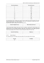
Phase
Setting
(Volts)
Tolerance
V element
Used for test
Blocked
Volts
NOTES
UVG
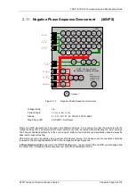
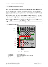
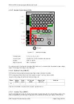
2.14.3 NPS Overvoltage (47)
7SR12
46
BC
46
NPS
(x2)
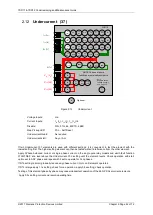
37
(x2)
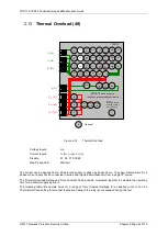
49
50
BF
51V
V
L1
(V
A
)
V
L2
(V
B
)
V
L3
(V
C
)
I
L1
(I
A
)
81
HBL
2
37
(x2)
49
50
BF
51V
I
L2
(I
B
)
81
HBL
2
37
(x2)
49
50
BF
51V
I
L3
(I
C
)
81
HBL
2
I
4
(I
G
)
74
T/
CCS
NOTE: The use of some
functions are mutually exclusive
67/
50
(x4)
67/
51
(x4)
67/
50N
(x4)
67/
50
(x4)
67/
50
(x4)
67/
51
(x4)
67/
51
(x4)
67/
51N
(x4)
67/
50
SEF
67/
51
SEF
27
59
(x4)
27
59
(x4)
27
59
(x4)
47
(x2)
79
Optional
59N
(x2)
Note:
Example shows
Voltage Config =
Van, Vbn, Vcn
60
CTS
60
VTS
50BF
51c
51c
51c
64H
81
(x4)
Figure 2-16
NPS Overvoltage
Voltage Inputs:
V
L1
(V
A
), V
L2
(V
B
), V
L3
(V
C
)
Current Inputs:
n/a apply zero current to stabilize other functions
Disable:
27/59, 59N, 60VTS
Map Pickup LED:
47-n - Self Reset
Summary of Contents for Argus 7SR11
Page 1: ...Energy Management 7SR11 7SR12 Argus Overcurrent Relay Reyrolle Protection Devices ...
Page 2: ......
Page 4: ...7SR11 7SR12 Argus Contents 2015 Siemens Protection Devices Limited Page 2 of 2 ...
Page 170: ...7SR120 Technical Manual Chapter 4 Page 2 of 84 2017 Siemens Protection Devices Limited ...
Page 174: ...7SR120 Technical Manual Chapter 4 Page 6 of 84 2017 Siemens Protection Devices Limited ...
Page 196: ...7SR120 Technical Manual Chapter 4 Page 28 of 84 2017 Siemens Protection Devices Limited ...
Page 242: ...7SR120 Technical Manual Chapter 4 Page 74 of 84 2017 Siemens Protection Devices Limited ...
Page 244: ...7SR120 Technical Manual Chapter 4 Page 76 of 84 2017 Siemens Protection Devices Limited ...
Page 246: ...7SR120 Technical Manual Chapter 4 Page 78 of 84 2017 Siemens Protection Devices Limited ...
Page 254: ...7SR11 7SR12 Installation Guide Chapter 5 Page 2 of 32 2017 Siemens Protection Devices Limited ...
Page 358: ...7SR11 7SR12 Applications Guide Page 2 of 48 2017 Siemens Protection Devices Limited ...
Page 405: ......


