background image

Main code

Sub code

Description

Ref. Page

26

08

Lens characteristics entry (at a time of lens replacement)
Because each lens has a variance in focal distance, the lens moving distance in any zoom mode must
correspond with the focal distance of the lens. The zoom ratio varies proportionate to the variance of
the lens focal distance.
To avoid focus problem, the class of the lens focal distance (refer to chart on page 7-11) is stored in the
memory using the test command. In a variable zoom mode, the lens moving distance that corresponds
to the lens focal distance is obtained on the basis of the data so as to produce the accurate zoom copy.

[7]-10-(6)

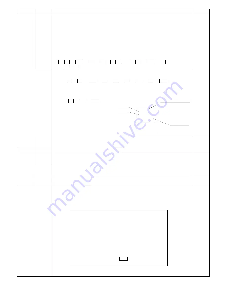
Setup method (26-08)

1

When the test command is executed, the presently stored preset code is displayed and the READY
lamp turns on.

2

After the READY lamp turned on, enter the lens number shown on the top of lens area and press
the PRINT switch to store the value in the memory. The READY lamp now turns off.

 C 

 =


 0/


 =


 2 

 6 

 PSW 

 8 

 PSW 

 1 

 4 

 PSW 

09

4/5 mirror characteristics entry (at a time of lens replacement)

[7]-10-(6)

1

Set the correction value for lens marked value based on "lens value vs. test command input."

Press  C 

 =


 0/


 =


 2 

 6 

 PSW 

 9 

 PSW  keys to execute

the test command 26-09.
As the READY lamp turns on, the previously set value 1 to 21 is shown.

2

Enter the new value on the keypad.
EX: If the value shown on the lens is +1, 2, enter "14."

Press the  1 

 4  

 PSW  keys.

10

AE original density setting
Used to set the original density. (Set value: 1 

 9)

Default: 2  Set to 9 if the density is extremely low.

27

01

PPC communication trouble

30

01

Monitoring main unit paper sensor 
Used to check the on/off state of paper sensor in the copier.
When the sensor turns on, the display reverses.

02

Monitoring paper cassette size
Used to check the on/off state of paper cassette size. When the switch turns on, the display reverses.

42

*

°

Developer counter clear
Reset the contents of the copy number counter of the installed developing unit.

43

*

When main code "43" is entered, the following message is displayed on the LCD. 

°

 Fusing temperature setting

Used to set the fusing temperature. 
When this simulation is executed, the currently set fusing temperature is displayed.
The fusing temperatures in the single copy mode and the duplex copy mode can be set individually. 
Use the message forward scroll key to select the mode. Use the ten key to set the temperature. 

SIMULATION No.43-

*

[1 

 1, 2 

 1]

INPUT1 

 10

1. 160°C

2. 165°C

3. 170°C

4. 175°C

5. 180°C

6. 185°C

7. 190°C

8. 195°C

9. 200°C

0. 205°C

[1 

 2, 2 

 2]

1. 160°C

2. 165°C

3. 170°C

4. 175°C

5. 180°C

6. 185°C

7. 190°C

8. 195°C

9. 200°C

0. 205°C

[1 

 2, 2 

 2] SETTING:PRESS

 ➡ 

KEY

901024
O. L
O. i
P. NO

+

 1.2

+

 2.4

12

0

TOPCON

0

(0-i)

Man ufac tu ring   date

Preset val ue

Label  contents

(0-L)

8 – 11

Summary of Contents for SF-2040

Page 1: ...TIONS SPECIFICATIONS 3 1 4 COMPONENT IDENTIFICATION 4 1 5 INSTALLATION 5 1 6 DISASSEMBLY AND REASSEMBLY 6 1 7 ADJUSTMENTS 7 1 8 SIMULATION AND DIAGNOSTICS 8 1 9 MAINTENANCE AND OTHERS 9 1 CONTENTS SHARP CORPORATION This document has been published to be used for after sales service only The contents are subject to change without notice ...

Page 2: ... 2 1 7 Multicopy 2 1 8 Magnification ratio 2 2 9 Exposure 2 2 10 Paper feed 2 2 11 Developing method 2 3 12 Charge method 2 3 13 Transfer method 2 3 14 Separation method 2 3 15 Fusing method 2 3 16 Cleaning method 2 3 17 Light source 2 3 18 Blanking areas 2 3 19 Automatic duplex 2 3 20 Paper receiving tray and finishing 2 3 21 Additional features 2 4 22 Power supply 2 4 23 Power consumption 2 4 24...

Page 3: ...aration corona wires 5 4 4 Installing accessories 5 4 A Install the copy receive tray 5 4 5 Setting up the upper paper cassette 5 5 A Remove the packing screw of the cassette 5 5 B Removing the cassette 5 5 C Change the size using the side plates F and R 5 5 D Insert the rear plate 5 5 E Set the size detect spacer 5 5 F Change the paper size indication plate 5 5 G Set the cassette 5 6 H Load paper...

Page 4: ...e sorter 5 19 4 Place the sorter on the sorter seat 5 20 5 Remove the rear cabinet panel from the copier and cut out the notch in the cabinet panel 5 20 6 Connect the sorter connectors 5 20 7 Reattach the rear cabinet panel 5 20 8 Reattach the front panel of the sorter 5 20 9 Adjust the clearance between the sorter and the copier 5 21 10 Set the mode 5 21 5 SF D23 5 21 1 Place the copier on the de...

Page 5: ... SF CM11 5 30 1 Remove the rear cabinet panel from the desk 5 30 2 Install the lift up unit 5 30 3 Remount the rear cabinet panel onto the desk 5 31 4 Remove the right cabinet panel from the front right cabinet panel of the desk 5 31 5 Remove the cover 5 31 6 Install the paper feed unit 5 31 7 Remove the packing screw from the paper cassette 5 31 8 Change the positions of the front and rear side p...

Page 6: ...ce Position of Lens 7 8 2 Adjusting the Reference Position of 4 and 5 Mirror 7 8 3 Adjusting the Longitudinal Magnification 7 8 4 Adjusting the Resolution 7 9 5 Adjusting the Lateral Magnification 7 10 6 Inputting the Lens Travel Correction Value 7 10 7 Correcting the Longitudinal Distortion 7 12 8 Correcting the Lateral Distortion 7 13 9 Adjusting the Center Deviation 7 14 10 Adjusting the Exposu...

Page 7: ...o maintenance 9 2 2 Alarm message 9 3 3 Setting the copy counter mode 9 5 3 Replacing the Ozone Filter 9 5 1 Replacing the suction ozone filter 9 5 4 Oil Grease Points 9 6 1 Gear of main driving unit 9 6 2 Gear of variable speed paper feed unit 9 6 3 Gear of paper feed driving unit 9 6 4 Fusing unit driving gear 9 6 5 Paper exit roller driving gear 9 6 6 Paper feed torque limiter 500 sheet cassett...

Page 8: ...ity and functionality 1 Use of a liquid crystal display with backlight 2 Department control counter standard provision max 50 depart ments 3 Use of key operator codes 3 High copy performance 1 First copy time 3 1sec 2 Job speed S S 100 D D 70 4 Options Refer to the system outline below 4 System outline Cassette for replacement SF CM11 Cassette SF IC11 Reversing automatic document feeder SF A55 Doc...

Page 9: ...3 sheets per minute 50 A4 portrait 40 sheets per minute 21 sheets per minute 200 33 sheets per minute 50 A4 landscape 31 sheets per minute 18 sheets per minute 200 27 sheets per minute 50 B5 portrait 40 sheets per minute 21 sheets per minute 200 33 sheets per minute 50 B5 landscape 31 sheets per minute 18 sheets per minute 200 27 sheets per minute 50 Ledger 22 sheets per minute 16 sheets per minut...

Page 10: ...56 80g m2 15 21 lbs Selection by way of guide replacement by the service engineer Front drawer in the same body ADU compatibility available Lower cassette Letter Letter R Legal Ledger Invoice 56 80g m2 15 21 lbs Selection by way of guide replacement by the service engineer By way of front inner cassette With the option inner cassette used Initial setting Japan Outside Japan Inch Outside Japan AB R...

Page 11: ...Automatic duplex Option SF DM11 Location Copier upper module slot Size AB series A3 B4 A4 A4R B5 B5R A5 Inch series Ledger Legal Letter Letter R Capacity 50 sheets below A4 or letter sizes or 30 sheets above B4 or Legal size Paper weight 56 to 80 g m2 15 to 21 Ibs 20 Paper receive tray and finishing Capacity of paper receive tray 250 sheets Finishing With option in use Finisher function Sorted bin...

Page 12: ...to start F From the energy save mode Auto tray switching F Priority selection of tray Vendor F Binding margin shift Width AB series Inch series Single sides to single sided 9mm 1 4 Double sided to single sided 9mm 1 4 Single sided to double sided front 9mm 1 4 Single sided to double sided reverse 9mm 1 4 Double sided to double sided front 9mm 1 4 Double sided to double sided reverse 9mm 1 4 Frame ...

Page 13: ...ice part 5 Lower roller kit Lower heat roller Fusing separation pawl Lower 1 2 160K SF 240LH 5 For replacement of the fusing separation pawl 80K life at every 80K use one which is treated as a service part 6 80K maintenance kit Cleaner blade Charging plate unit Drum separation pawl unit 1 1 1 80K SF 235KA1 5 Products are shipped from out division Treated as parts in SEC 222BL 10 222CB For receptio...

Page 14: ...0g 10 16 5K 10 A3SF240LT1 1 SF 240T1 10 SF 240LT1 4 80K maintenance kit Upper cleaning roller Lower cleaning roller Toner collection container Fusing separation pawl Upper Fusing separation pawl Lower Screen grid Cleaner blade Charging plate unit Drum separation pawl unit 1 1 4 4 2 1 1 1 1 80K A3SF240KA 1 5 160K maintenance kit Upper heat roller Lower heat roller Toner reception seal DV seal Fusin...

Page 15: ...requested 1 Standard conditions Recommended temperature range at 20 to 25 Centigrade 68 to 77 degrees F and humidity range at 65 5 RH 2 Operating conditions 3 Shipping conditions 4 Consumables storage conditions 60 20 30 C 35 C 80 Temperature 15 C Humidity 60 20 30 C 45 C 90 Temperature 20 C Humidity 20 40 C 90 Temperature 5 C Humidity 2 7 ...

Page 16: ...ogram Japan only Mixed paper feed Random paper feed allowed Power supply Supplied from the copier Dimensions 600 W 525 D 170 H mm Weight Approx 15kg 2 SF S15 Name 20 bin sorter No of bins 20 bins Paper collection Copy face up Capacity per bin Max 50 sheets 100 sheets Top bin Allowable paper size weight for collating Max A3 Min B5 Min A6 for non sort Non sort 52 128g m 2 Sort Grouping 56 80g m 2 Po...

Page 17: ...Paper weight 56 80g m 2 Capacity A3 B4 30 sheets A4 B5 50 sheets Power source Supplied from the copier Weight About 6kg 6 SF CM11 Cassette module Equivalent to the upper cassette of the copier body The optional 2 cassette paper feed desk can be attached 7 SF IC11 Inner cassette Paper cassette for replacement of the lower cassette 8 SF 71A counter SF 71B socket Personal counter 9 Other counters Car...

Page 18: ...n panel 5 Document glass 6 Paper clip tray 7 Manual feed tray paper guides 8 Manual feed tray 9 Exit area cover F Power switch G Duplex module or 500 sheet paper drawer optional H Lower paper tray I Front cover J Toner collecting container cover K Handles L Side cover 1 2 3 4 5 6 7 9 10 11 12 13 14 15 16 8 4 1 ...

Page 19: ...M Fusing section N Transport section open close lever O Photoconductor drum P Charger Q Toner box R Toner box lever S Roller rotating knob T Toner collection container 16 17 18 18 20 21 22 23 4 2 ...

Page 20: ...LECT key W Original size display X 10 key pad Y AUDIT CLEAR key Z Clear key CLEAR ALL key START key and indicator P 0 C CA COVERS ERASE MARGIN SHIFT DUALPAGE COPY SORTER ORIGINAL TOCOPY EVEN NUMBER ODD NUMBER ORIGINALS 1 0 0 AUTO IMAGE ZOOM 100 SORT STAPLE SORT GROUP PRE COUNT ORIGINALS 0 0 1 1 1 AUTO MANUAL PHOTO EXPOSURE LIGHT DARK AUTO EXPOSURE COPY RATIO 1 0 0 00x17 1 8 x11 0 AUTOPAPER SELECT ...

Page 21: ...wer separator pawl U Upper separator pawl V Upper cleaning roller W Fuser thermistor X Delivery select gate Y Manual feed takeup roller Z Manual feed paper feed roller Counter manual feed roller Transport roller upper Transport roller lower Upper paper feed roller _ Upper paper feed reverse roller Upper paper takeup roller a Lower paper feed roller b Lower paper feed reverse roller c Lower paper t...

Page 22: ...ing paper feed roller 4 CPFC2 Lower cassette paper feed clutch For actuating paper feed roller 5 MPFS Manual paper feed solenoid For tensioning takeup roller 7 TRCH Transport roller clutch fast For actuating transport roller fast 8 RRC Resist roller clutch For actuating resist roller 9 PSPS Paper separation solenoid For actuating paper separation solenoid F DGS Duplex copy gate solenoid For actuat...

Page 23: ...G PPD1 Transmissive photosensor Paper transport sensor 1 Low when paper passes over H PED1 Transmissive photosensor Manual feed paper sensor Low when paper passes over I TFD Transmissive photosensor Full waste toner sensor Low when full waste toner detected J LUD1 Transmissive photosensor Upper cassette liftup sensor Low when lift plate detected K PED2 Transmissive photosensor Upper cassette paper...

Page 24: ...ynchronous Supplying toner 6 LUM1 Upper cassette liftup motor DC brush Lifting upper paper feed cassette baseplate 7 LUM2 Lower cassette liftup motor DC brush Lifting lower paper feed cassette baseplate 8 CFM Cooling fan motor DC brushless Cooling optical system 9 VFM Ventilation fan motor DC brushless Ventilating fuser area F SFM Suction fan motor DC brushless Ventilating process unit area aid in...

Page 25: ... size 9 Liftup motor PWB Common Driving paper cassette bottom plate liftup F DC power supply unit 100V 200V series Supplying DC power G High voltage transformer Common Supplying process unit high voltage and developing bias voltage H Discharge lamp Common Driving discharge lamps I Process control VR PWB Common Process sensor sensitivity adjustment J Manual feed paper size sensor PWB Japan Export P...

Page 26: ...PPD2 Transimissive photosensor ADU paper transport sensor 2 High when paper detected 5 DTPID Transimissive photosensor ADU tray sensor High when paper detected 6 DPFD Transimissive photosensor ADU paper entry sensor High when paper detected 7 PAM2 DC stepping motor ADU rear plate motor 8 PAM1 DC stepping motor ADU alignment plate motor 9 DPFC Magnetic clutch ADU paper feed clutch F DRRC Magnetic c...

Page 27: ...9 Desk unit SF D23 11 12 16 17 13 18 10 9 8 7 6 2 5 4 3 1 23 21 22 19 20 14 15 4 10 ...

Page 28: ...l sensor 2 Photo interrupter Cassette 2 paper height control H level when interrupted H LMS2 Limit sensor 2 Photo interrupter Prevention against excessive height of cassette 2 paper H level when interrupted I DPOD2 Resist sensor 2 Photo interrupter Paper pass detection Paper in L level J E2CLK Elevator motor 2 clock sensor Photo interrupter Elevator motor 2 encoder clock detection Pulse output K E...

Page 29: ...usty poorly ventilated subject to extreme temperature or humidity changes e g near an air conditioner or heater 4 Ensure that the area chosen for the machine location is level 5 Be sure to allow the required space around the machine for ser vicing and proper ventilation A small amount of ozone is produced within the copier during operation The emission level is insufficient to cause any health haz...

Page 30: ...ting knob Push on the front panel and gently remove the fuser unit Do not let the locator pins under the fuser unit hit the ribs on the front cover 5 Hold the fuser unit hand carry strap and remove the fuser unit B Tensioning the heat roller Move the tension levers on both sides of the fuser unit to the position shown in the figure With this tension is applied to the upper and lower heat rollers C...

Page 31: ...Make sure now that the locator pins of the copier are firmly engaged into two locator holes of the fuser unit mounting bracket Secure fuser unit with two screw removed in 2 of A and close the paper exit Replace the front panel band that removed in 1 of A Close the paper exit cover 3 Cleaning corona units A Clean the main corona unit 1 Push down the hook of the main corona unit while removing the m...

Page 32: ... slide the separation corona in the direction of the arrow and remove the separation corona guide from the corona housing 3 Squeeze the transfer corona wire with the corona wire cleaner Move the cleaner in the direction of the arrow to clean the wire 4 Install the separation corona guide to the corona housing Insert the corona assembly along the guide of the transfer separation corona unit Rotate ...

Page 33: ...n shown with notches and secure with the two screws D Insert the rear plate Remove the rear plate and set the plate into the position indicated for the desired paper sixe E Set the size detect spacer Change the position of the size detect spacer Move the spacer to the appropriate positions F Change the paper size indication plate Remove the paper size indication plate Install the plate so the size...

Page 34: ...he size using the side plates F and R set to A3 position at the factory Set the plates into the appropriate positions and secure wach plate with two screws C Change the size of the rear plate Remove the rear plate Set the plate into the position indicated for the desired paper size D Set the size detect spacer Change the position of the size detect spacer Move the size detect spacers to the approp...

Page 35: ...ox until it stops 3 Slide the developing unit lock lever in the arrow direction to release lock and hold the toner box lever and pull out the developing unit until it stops Note When lock is released and the developing unit becomes free to move let go of the developing unit lock lever 4 Hold the carry strap of the developing unit and slide the develop ing unit lock lever in the arrow direction to ...

Page 36: ...body A Developing unit level adjustment 1 Perform the key operations of simulation 25 2 Simulation 25 will be completed in 3 minutes Note If the simulation is cancelled halfway auto scanning can not be performed Do not cancel it halfway 3 Cancel simulation 25 with the CA key 10 Toner supply A Toner supply 1 Open the front cabinet 2 Tilt down the toner box lever towards you and pull out the toner b...

Page 37: ...e arrow direction to remove 9 Push the toner box slowly to the original position and lift the toner box lever Toner supply is completed with the above procedure Close the front cabinet 11 Label attachment A Label attachment Attach the magnification ratio select label packed together with the Operation Manual to the position shown below When attaching to the copier with the original cover When atta...

Page 38: ... ADF with the two ADF securing screws 2 Adjust the angle of ADF Loosen the two fixed screws for the angle adjusting panel which are located on the hinge angle and then fasten the loosened screws while raising the angle adjusting panel completely ADF tray ADF mounting screws 2pcs ADF securing screws 2pcs Cut outs Upper rear cabinet panel ADF mounting screw ADF mounting screw ADF securing screw ADF ...

Page 39: ...nt setting to be displayed If only the SF S53 is being set continue by performing the follow ing key operation to complete the mode setting If the mode is being set for a combination of options add up the numerical values of the options to be set see the table below and input the total sum Example When setting SF S53 and SF A55 the total sum of their values is 11 1 10 Therefore perform the fol low...

Page 40: ...gle sided double sided and light weight paper Setup example 1 If the lead edge of the original was still not to the stopper enter an optimum value 2 If the image at the lead edge of the original were to deform enter an optimum value to move to the glass side 3 If the original were to override the stopper enter an optimum value to move it to the glass side 3 SF S53 Center of original Center of copy...

Page 41: ...m around the copier for work space Remove the securing fixtures and attach the caster spacers When performed on the skid Remove the securing fixtures 2 Remove the caster screws 2 per caster and take off the 4 casters Next attach the casters and caster spacers using 2 screws each M4 x 50 as shown in the figure Rail mounting plate 1 Green label 1 Support guide 1 Stapling location label A 1 Stapling ...

Page 42: ...te Remove the screws 2 from the copier s upper left cabinet panel Attach the sorter mounting plate with the 2 sorter mounting plate screws M4 x 12 The sorter mounting plate screw holes are elongated tighten the screws so that the sorter mounting plate hangs down in its lowest position 2 Attach the support guide Attach the support guide by attaching its pawls 2 locations to the inside of the copier...

Page 43: ...r can be attached and detached correctly 1 Latch and unlatch the staple sorter from the copier to confirm that it moves smoothly 2 Confirm that the staple sorter locks into place beside the copier If not adjust the height of the sorter mounting plate until the staple sorter locks securely into place 8 Remove the copier s rear cabinet panel and cut off the cut portion of the left cabinet Remove the...

Page 44: ... and RADF as shown in the figure Copier RADF 12 Affix the green label Lifting up on the staple sorter s release lever separate the sorter from the copier Next affix the green label to the paper output section handle as shown in the figure Holding the staple sorter s release lever return the sorter to its original position At this time confirm that the staple sorter locks securely into place beside...

Page 45: ... not been stapled or the stapler is jammed adjust the staples by performing one of the following proce dures If copies have not been stapled 1 Remove the staple cartridge Open the stapler cover lift up on the staple cartridge and remove it by pulling in the direction of the arrow 2 Check the staple cartridge Confirm that the sheets of staples in the cartridge are properly stack ed If not slide the...

Page 46: ...he stapling section release lever to its original position 5 Reinstall the staple unit Reinstall the staple unit in its original location using the mounting screw to secure it in place Then close the stapler cover 6 Confirm that papers are stapled correctly Place a set of papers in the 2nd bin below the non sort bin check the stapling location and then press the manual staple key when it lights up...

Page 47: ...mounting screws A which were secured to the desk and then use the one sorter seat mounting screw B to secure the sorter seat mounting fixiture as shown 3 Remove the front panel of the sorter Loosen the four mounting screws in the front panel of the sorter and remove the panel SF S15 Parts list Sorter seat Support guide Sorter seat mounting fixture 1 pc Sorter seat mounting screws A 2 pcs Sorter se...

Page 48: ...e of the copier Connect the 6 pin and 10 pin sorter connectors to the 6 pin and 10 pin connectors of the copier and insert the tie band into the hole under the board installation part 7 Reattach the rear cabinet panel Use the four mounting screws to reattach the rear cabinet panel removed in step 4 in its original position 8 Reattach the front panel of the sorter Use the four mounting screws to re...

Page 49: ... up the total of the setting values for all the peripheral devices to be set from the table shown below and set theat total value SF A55 1 SF D23 4 SF S53 10 SF S15 10 5 SF D23 Be sure to unplug the copier before carrying out the following procedures 1 Place the copier on the desk Place the copier on the desk so that the feet of thecopier fit into the corresponding holes in the desk When doing thi...

Page 50: ...er into the connector on the desk Note that the temporary connector will no longer be used 5 Remount the rear coverlet of the copier Return the rear coverlet to its original position and use its mounting screw to mount it 6 Secure the desk on the floor Turn clockwise the two adjusters at the lower front of the desk to lower them to the floor and secure the desk in place Use the caster lock levers ...

Page 51: ...crew per guide in the positions corresponding to the desired paper size 9 Adjust the side guides Remove the mounting screws one per guide holding the right and left paper side guides in place Use the mounting screws to secure the right and left paper size guides one screw per guide in the positions corresponding to the paper size which has been set Mounting screws Front paper guide example A4 sett...

Page 52: ...n the maximum height line indicated on the cas sette Next place paper in the left paper cassette When doing this do not stack the paper higher than the maximum height line indicated on the cassette Grasp the cassette by the handle and gently push it all the way into the desk as far as it will go Plug the copier into a grounded outlet and turn the power switch on Then follow the procedure below 13 ...

Page 53: ...mounting screws attached to the cassette and adjust it following the prcedure below Note When mounting the center adjuster make sure that the mounting screws are positioned in the same spot in their respective slots When off center as shown in fig 1 Move the center adjuster in direction A and secure it with the two mounting screws Make a copy to check whether it is centered properly When off cente...

Page 54: ...redsize and secure the side plates with fixing screws 2 pcs each 3 To change the size position of the rear end plate Remove the rear end plate from its rear storage place and insert this into the cassette main unit for the desired size When you switch the size to A5 or 81 2 x 51 2 fix this plate to the rotary plate by using the screw that is attached to the rear end plate 4 To set the size detecti...

Page 55: ...h front and rear faces of the paper size indication plate 7 To install the cassette main unit on the paper tray Install the cassette main unit by putting the four projections into the corresponding holes of the paper tray 7 SF DM11 Before performing the following procedure be sure to remove the power plug of the copier main unit 1 To remove the rear cabinet of the copier main unit Remove the four ...

Page 56: ... the storage cover for the toner collecting container then remove the toner collecting container by pulling out and pressing down on it at the same time 5 To remove the cover plate Remove the screw that fixes the cover plate and remove the cover plate 6 To install the ADU unit Install the ADU unit by inserting the guides to the guide rails At this time the wheel for the left guide of the ADU unit ...

Page 57: ...rocedure to adjust the matching guide A Set the mode using the following key operation on the copier main unit Then current set value is displayed B To set the adjustment mode input the set value as shown below after the operation above Example To set a value 5 with one digit perform the following operation Example To set a value 15 with two digit perform the following opeartion Changing the set v...

Page 58: ...nto the two positioning bosses then use two type A mounting screws and one type B mounting screw to secure the lift up unit Connect the black relay harness connector comes included with SF CM11 to the lift up unit then connect the white connector to the circuit board Slip the relay connector into the cord clip for storage Note There are type A and type B lift up units If you have the type A unit c...

Page 59: ...e of approximately 30 slide it all the way back as far as it will go Fit the paper feed unit into the positioning bosses two locations on the desk frame and secure it with one mounting screw B 7 Remove the packing screw from the paper cassette Remove the packing screw which secures the paper pressure plate inside the paper cassette The paper size is set to A4 for AB system and 81 2 x 14 for inch s...

Page 60: ...icator 12 Fit the paper cassette guides into the guide rails Insert the paper cassette by fitting the guides of the paper cassette into the guide rails When doing this insert the paper cassette all the way in so that the cassette s left guide roller goes past the stopper on the guide rail 13 Mount the right stopper Fit the right stopper into the notch in front of the paper cassette s right guide r...

Page 61: ...djust any center misalignment Make a copy and if there is any center misalignment such as that shown in Fig 1 or Fig 2 loosen the four screws indicated by the arrows which secure the front cabinet panel NOTE The mounting screws a and b will be in the symmetrical positions when they are tightened as shown right If misaligned as shown in Fig 1 Move the front cabinet panel in direction A and retighte...

Page 62: ...e the blank lamp PWB Unfasten the discharge lamp harness connector Remove the discharge lamp unit 1 screw Remove the cleaning blade 3 blue screws Separation solenoid Separator pawl Unfasten the harness connector from the separation solenoid Remove the separation solenoid Remove the separation pawl unit from the process unit Counter roller Remove the DR mark sensor PWB from the BL PWB unit 1 screw ...

Page 63: ...5 5 C F 10 D 7 6 11 G E 8 9 H 12 6 2 ...

Page 64: ...ove the connection gearwheel 1 E ring Remove the manual feed drive gearwheel 1 C ring Remove the spring clutch small 2 E rings 1 pin Remove the spring 1 spring Remove the front side bushing of the drive roller shaft assy 1 E ring 1 clutch spring bushing Remove the drive roller shaft assy Remove the paper feed roller from the drive roller shaft assy 3 E rings 1 connection gearwheel 1 pin Remove the...

Page 65: ...3 B 3 E 13 C 4 5 6 7 8 F 14 D 10 11 9 6 4 ...

Page 66: ...ngages from the frame Remove the manually set E ring Remove the pickup roller lever Remove the paper feed roller NOTE Remove the takeup roller NOTE Remove the tension spring Remove the manually set E ring Move the shaft including the gearwheel Remove the counter roller Remove the spring Remove the solenoid lever Remove the solenoid on the line The one way clutch is on the rear frame side clutch si...

Page 67: ...2 1 3 A D 9 8 11 10 B 4 5 E 12 13 14 C 7 6 6 6 ...

Page 68: ...ate unit remove the DV tank the front cabinet the process unit and the upper cassette ADU unit in advance Before removing the upper cassette it is advisable to remove the paper feed unit in advance Since the fuser unit will serve as the guide rail for removing and assembling the transport base plate do not remove it Open the right cabinet 10 Remove the connecting plate 5 in Fig F 2 screws 11 Remov...

Page 69: ...A a 1 1 D 4 4 B 1 b 1 1 E 5 5 7 6 8 9 8 5 C 2 3 3 F 5 11 12 6 8 ...

Page 70: ...ler Clean thermistor surface using alcohol Open the lower pawl holder bracket assy 2 screws Remove the lower heat roller assy Remove the lower separation pawls When installing the lower heat roller the pawls must be positioned away from the roller before closing the lower pawl holding plate then restore pawls to proper position after installing roller Discharge brush The discharge brush must be in...

Page 71: ...1 2 3 3 4 5 A D 13 11 10 7 6 6 7 B E 14 8 12 9 C F 15 G 16 16 6 10 ...

Page 72: ...t and rear side two counter roller tension springs Front frame Rear frame Spring color Black White Spring tension Strong Weak Remove the counter roller Remove the clutch retaining plate 1 screw Loosen the setscrew and remove the clutch Remove the takeup roller drive shaft 2 on front 1 on rear Push down the spring holder and remove the takeup roller unit from ADU Remove the takeup roller arm side E...

Page 73: ...A a 1 D 11 10 10 9 8 B 4 2 3 E 13 12 12 C 5 7 6 7 6 12 ...

Page 74: ...e the paper feed drive unit 4 screws Remove the joint plate 2 screws Remove the main drive side pulley holding E ring then remove the drive belt Remove the variable paper feed speed unit 4 screws Remove the variable speed clutch unit Unfasten the high voltage unit connectors 6 connectors and remove the ground harness from the copier chassis 1 screw each Remove the high voltage PWB from the suction...

Page 75: ...C 4 F 9 9 9 10 9 5 6 D G 11 E 8 7 6 14 ...

Page 76: ...he copier 6 screws Remove the rear side screw of the left side panel 1 screw Remove the AC power supply board 2 screws 6 connectors Remove the DC power supply PWB 5 screws 1 connector Remove the paper exit gate solenoid 2 screws 2 connectors DC power PWB identification 100V system White label 200V system Red label 6 15 ...

Page 77: ...ve the screws that hold the magnetic catch plate one each on two locations Remove the operation panel unit Remove the operation panel from the operation panel unit 15 screws 6 connectors Remove the document size sensor board screw 8 9 10 11 LCD unit Remove the LCD control PWB from the operation panel unit 3 screws 1 connector Remove the LCD control PWB mounting angle from the operation panel unit ...

Page 78: ...Volume PWB 8 9 10 10 6 17 ...

Page 79: ...e upper dark box cover 2 screw Remove the wire holding plates found on both frame sides of the copy lamp unit then remove wires from the side plates F R Rotate the copy lamp unit to remove Remove the mirror base wire from the 2 3 mirror base unit Move the 2 3 mirror base unit to the square hole a on the front side of the optical baseplate then rotate it to remove Remove the rear panel 6 screw Reco...

Page 80: ...C 5 F 11 P D F R 7 6 6 12 13 G 12 13 E 8 9 a 8 H 14 6 19 ...

Page 81: ...the pulley groove in the paper feed side 4 Pass the mirror base wire under mirror base B and wind it around the winding pulley At that time fix the wire groove section in the winding pulley to the upper position wind the mirror base wire 9 times and put the 8th winding in the groove The first winding position should be 9 10mm toward the body frame from the pulley groove section 5 Pass the mirror b...

Page 82: ...about 4mm Perform the same procedures for the front frame side and the rear frame side Copy lamp unit installing position 1 Pass the front rear mirror base drive wire between the copy lamp unit frame and the wire fixing plate In this case do not tighten the wire fixing screw 2 Press the copy lamp unit onto the positioning plate and tighten the wire fixing plate No 2 3 mirror base unit installing p...

Page 83: ...amage the developing doctor blade or the magnet roller during insertion of the feeler gauge Tool UKOGM0075CSZZ Feeler gauge 2 Position Adjustment of Developing Magnet Roller Main Pole 1 Remove the 4 screws and the 5 pin connector which connect the developer tank to the toner hopper and remove the toner hopper Put developing unit on a flat surface 2 Thread a needle or pin as shown in the figure on ...

Page 84: ...No gap must exist at between the V ring and the roller 3 When attaching φ8 ring PRNGP0013FCZZ φ8 ring PRNGP0022FCZZ and φ6 ring PRNGP0015FCZZ to the developing magnet roller 1 the direction of the V ring must be as shown in the upper figure 2 no gap must exist at between the V ring and the roller 5 Notes on applying the developing side seals front and rear 1 The side seal must be applied on a surf...

Page 85: ... 0 5 mm Half notch of the adjusting cam lamp movement 0 25 mm 2 Adjustment of High Voltage Output Balance A Applying the Special Measuring Tool Digital multimeter or ampere meter Note use a multimeter with measuring range of 0 to 100 µA and error of 1 or less A B IA BI 1mm Backward The blank lamp unit moves forward The blank lamp unit moves backward Forward UKOG 0110FCZZ UK0G 0110FCZZ A QCLIZ0005F...

Page 86: ...rame must be 5 0 µA or less a Turn on the main switch and perform Simulation 8 06 THVG will be ON for approx 30 seconds b Measure the drum current on the front and rear frame side If the microswitch is OFF the drum current on the side of front frame is indicated If the microswitch if ON the drum current on the side of rear frame is indicated c Check that the difference in current between both side...

Page 87: ...heck the grid voltage using Test command 44 11 The grid voltage is displayed in two digits on the copy quantity display The display changes in the sequence of N TSM P mode when the message feed key is pressed Mode Figure Grid voltage Normal 860 860V TSM 755 755V Photo 610 610V NORMAL Normal mode Set value 860 860V output To decrease the measurement voltage make the set value smaller 1 step 1V To i...

Page 88: ...R502 so that the output monitoring voltage bias BCDCCP of the separa tion charger is 100 10 Vdc 3 Notes on maintenance for high voltage units A Electrostatic Charger Unit 1 Do not distort nor stain the screen grid during handling Be sure that the screen grid is secured in place 2 The teeth of the saw tooth assembly must be free of distortion 3 Do not touch the inside of the MC case saw tooth assem...

Page 89: ...cs Focus Adjust reference position of 4 and 5 mirror Magnification Adjust longitudinal magnification Adjust lateral magnification Magnification in focus at reduced x 0 50 and enlarged x 2 00 copy Adjust characteristic values of lens irregularity of focal length Image distortion center deviation Image distortion Correct lateral distortion Center deviation Position of exposure balancing blank lamp i...

Page 90: ...2 value to be input If the preset reference value is larger than the mid value 42 the 4 and 5 mirrors are set further away from lens If the preset reference value is smaller than mid value 42 the mirrors are set closer to lens To select inputs for No 4 5 mirror reference position and the lens reference position adjustment 7 3 1 use key scrol dis play key The previously set figures are displayed on...

Page 91: ...amp is lit a preset value is indicated 2 If no preset value exists set a reference value according to 2 Adjusting the reference position of 4 and 5 mirror Then take a copy of UKOG 0089CSZZ and check the resolution 3 When changing a preset value PSW Checking Procedure After adjusting the reference position of 4 and 5 mirror check as follows 1 Set the test chart UKOG 0089CSZZ or a resolution test ch...

Page 92: ...ENT PAPER TRANSPORT DIRECTION MAGNIFICATION RATIO ADJUSTMENT 5 20 35 6 Inputting the Lens Travel Correction Value Simulation 26 08 26 09 Inputting the lens characteristics The lens varies in focal length for each machine The lens travel is required to correspond to the focal length of the lens If the lens travels at a magnification would be constant among the machines in spite of the focal length ...

Page 93: ...5 4 5 5 15 5 2 5 3 2 6 2 7 16 27 5 0 5 1 17 4 8 4 9 2 4 2 5 18 28 17 4 4 5 1 4 6 4 7 19 4 4 4 5 2 2 2 3 20 29 4 2 4 3 21 4 0 4 1 2 0 2 1 22 30 16 3 6 4 3 3 8 3 9 23 3 6 3 7 1 8 1 9 24 31 3 4 3 5 25 3 2 3 3 1 6 1 7 26 32 15 2 8 3 5 3 0 3 1 27 2 8 2 9 1 4 1 5 28 33 2 6 2 7 29 2 4 2 5 1 2 1 3 30 34 14 2 0 2 7 2 2 2 3 31 2 0 2 1 1 0 1 1 32 35 1 8 1 9 33 1 6 1 7 0 8 0 9 34 36 13 1 2 1 9 1 4 1 5 35 1 2 ...

Page 94: ...nt frame A3 size or 11 x 17 blank paper Lens display value Correction reference value Lens display value Oi Oi OL No 4 5 mirror focus adjustment 45MB 48 01 Vertical magnification ratio adjustment 48 01 Lens characteristics input value 26 08 No 4 5 mirror characteristics input value 26 09 2 5 2 4 1 3 1 2 54 46 8 2 8 1 9 2 7 2 6 55 2 9 2 8 1 5 1 4 56 47 3 1 3 0 57 3 3 3 2 1 7 1 6 58 48 7 3 6 2 7 3 5...

Page 95: ... pulley 6 Repeat steps 1 to 3 7 If La is not equal to Lb repeat steps 4 and 5 until La Lb 8 Correcting the Lateral Distortion If the lateral distortion occurs without the longitudinal distortion dis tortion in the mirror base scanning direction the lateral distortion can be corrected by adjusting the height of 2 and 3 mirror base and or the eccentric roller of 4 and 5 mirror base The correction pr...

Page 96: ...aper discharge side by one half of Ld Lc Grasping the grip of the mirror base rail move the mirror base rail 2 Adjust the eccentric roller as described in 1 until La Lb and Lc Ld 3 After adjustment manually rotate the mirror base driving pulley to check that the mirror base A and B do not come into contact with each other during full scanning motion Note If the mirror base rail is moved excessivel...

Page 97: ...0 PSW 1 PSW to perform Simulation 50 When the ready lamp goes on a preset value ranging from 1 to 99 is indicated Content of RRC A 3 Set values of both A and B to 0 and take a copy of the scale at magnification of 100 and 200 respectively A full size 100 copy can be taken by typing 0 0 0 0 PSW A enlarged 200 copy can be taken by typing ENLARGE After the lens moves ready lamp ON PSW 4 Measure a dis...

Page 98: ...tion 50 01 and not the final value 8 Set a scale and an A3 size 11 x 17 blank paper on the original table as shown in the figure 9 Operate the scrol display key to set to the void adjustment mode of the LCD F Take a copy Type a value for adjusting the end void area of the full size copy so that measured with the scale image the solid edge is 1 4 mm away from the paper end The key operation PSW pro...

Page 99: ...edge deviation at 100 magnification mm 3 digit Indication example of copy quantity indicator 42 5 mm 4 2 5 indicated as 2 5 4 Using the scrol display key and ten keys set both A and B values to 0 and take a copy at magnification 100 and 200 respectively An 100 copy can be taken by typing 0 0 0 0 0 0 PSW A 200 copy can be taken by typing ENLARGE After the lens moves ready lamp ON PSW 5 Measure the ...

Page 100: ...system dirt When Simulation 46 01 is performed each mode cor rection is initialized When performing Simulation 46 01 perform the adjustments of all modes This machine automatically performs the correction to the sensitivity due to photoconductor aging When a copy is made in Simulation 46 01 the correction state will be initialized 3 Procedure for copy density adjustment 1 Initial setting of auto e...

Page 101: ...or 0 5 of UGOG 0089CSZZ has slightly copied and 5 0 3 is not copied When light Decrease the value shown on the copy quantity indicator When dark Increase the value shown on the copy quantity indicator available values 1 99 EXPOSURE LEVEL ADJUSTMENT ME1 ME5 TS1 TS5 PE1 PE5 AE1 AE5 AE1 TS AE5 TS 3 When the copy density meets the above requirement press key to highlight ME5 4 Make a copy Check that t...

Page 102: ... on the copy quantity indicator When dark Increase the value shown on the copy quantity indicator EXPOSURE LEVEL ADJUSTMENT ME1 ME5 TS1 TS5 PE1 PE5 AE1 AE5 AE1 TS AE5 TS 2 Adjusting the auto TSM mode 1 Press key to highlight AE1 TS 2 Enter 0 for AE1 TS EXPOSURE LEVEL ADJUSTMENT ME1 ME5 TS1 TS5 PE1 PE5 AE1 AE5 AE1 TS AE5 TS 3 Press key to highlight AE5 TS 4 Perform adjustments similarly to auto exp...

Page 103: ... output 300 V manual exposure 1 Perform Simulation 8 01 B Adjusting the manual exposure copy density Perform Simulation 46 01 ME 1 ME 5 C Adjusting the TSM mode TS 1 TS 5 D Adjusting the copy density in photo mode PE 1 UKOG 0162FCZZ DENSITY No 1 2 3 4 5 6 7 8 9 10 W UKOG 0089CSZZ DENSITY No 0 1 0 2 0 3 0 5 1 9 0 KODAK GRAY SCALE 1 2 3 4 19 A SHARP CORPORATION MADE IN JAPAN Not copied Slightly copi...

Page 104: ...uto exposure copy density 1 Normal mode AE 1 Input 0 AE 5 2 TSM mode AE 1 Input 0 AE 2 1 10 W 2 3 4 5 6 7 8 9 Not copied Slightly copied 1 10 W 2 3 4 5 6 7 8 9 Not copied Slightly copied 1 10 W 2 3 4 5 6 7 8 9 Not copied Slightly copied 7 22 ...

Page 105: ...Standard value 204 10 3 Execute simulation No 44 6 compulsory execution of process control 4 Execute simulation No 46 1 copy exposure adjustment Execute the copy exposure adjustment according to the proce dure of 8 5 E Adjustments when replacing the developer and the drum photoconductor Complete replacement of the drum Complete replacement of the developer Turn on the power 1 Execute simulation No...

Page 106: ... drum surface by incomplete cleaning Check the cleaning blade and the photoconductor drum surface and replace them if necessary Drum mark sensor DM sensing level is not adjusted Improper drum drum without mark Execute simulation No 44 2 Set to 204 10 with VR1 Drum mark sensor DM PWB trouble Process control VR PWB trouble F2 35 Process control operation failure When 1 or 2 is detected process contr...

Page 107: ...ndow The diagnostic is automatically terminated after the doorswitch operation ON OFF ON except H and U2 code 3 Simulation execution procedure List of the test commands 1 1 1 YES YES NO NO NO YES 1 Press the CLEAR key 2 Press the PAUSE key 3 Press the 0 ΚΕΨ 4 Press the PAUSE key As the copy number window number disappears the control becomes ready for entry of a simulation number Enter the require...

Page 108: ...tch activation 11 Paper feed solenoid activation 13 12 Paper feed clutch activation 14 16 17 Transport changeover clutch activation SF D23 only 18 Separate clutch activation SF D23 only 05 01 Operation panel display check 02 Fuser lamp check 03 Copy lamp check 04 BL DL check 06 02 Separation pawl solenoid operation check 07 01 Warm up time display and aging with jam detection 04 Warm up disabled 0...

Page 109: ...ck 02 Document size sensor adjustment 03 Document sensor light receiving level adjustment 42 Developer counter clear 43 Fusing temperature setting 44 01 Correction mode setting 02 Drum mark sensor sensitivity adjustment 03 Image density sensor sensitivity adjustment 05 Test mode 06 Compulsory execution of process control 07 Drum mark sensor image density sensor gain select check 09 Process control...

Page 110: ...ion sensor 03 Used to test the zoom lens movement The zoom ratio is displayed on the zoom ratio window 04 Used to test the zoom lens in the aging test mode Test command 01 03 are repeated to test 02 01 Used to test the action of the RADF The aging test starts when the document presence sensor is manually turned on 02 This is the test command used to test RADF sensors On off state of sensor can be ...

Page 111: ... the sorter individual load check Transport motor rotation 04 Indexer motor rotation returns to the home position at first then stops at each bin location Bin 1 to Bin 21 moving up and down Sorter bin moving 05 Fan motor rotation in the case of SF S15 only 06 Gate solenoid ON 07 Offset solenoid in the case of SF S53 08 Stapler motor rotation the paper is stapled once when there is a paper in the s...

Page 112: ... the copy lamp intensity can be changed to the power set on the exposure setup key for a period of 6 25 seconds Use care not to damage original cover or RADF belt Refrain from repeating this test command without waiting for lamp and glass to cool 04 This is the test command used to check activation of the discharge lamp DL and the blank lamps BL The discharge lamp DL turns on for 30 seconds Each b...

Page 113: ...output the machine automatically goes into the sub code input wait state This is the test command used to check the transfer corona output THV The transfer corona output continues for 30 seconds 7 4 B Standard transfer corona output is 57µA 4µA F R difference Max 5µA 07 Separation corona output After delivering the output the machine automatically goes into the sub code input wait state This is th...

Page 114: ...e preset cycle counter 03 JAM memory display JAM map display Displays the causes positions of JAM occurred in copy operation Max 50 JAMs from the recent one To check the history of JAM cause press the message forward feed key Table of JAM code JAM CODE F SECTION F DESCRIPTION SECTION F DESCRIPTION Main body manual paper feed 1 4 PPD2 not reached Transport ON JAM 8 1 DPPD1 not reached Main body upp...

Page 115: ...ter value of each cassette 24 01 Misfeed map memory and total misfeed counter clear 03 RADF counter clear The contents of the copy number counter is reset for the RADF It is mandatory to clear the memory contents after the maintenance is completed 04 Duplex counter clear The contents of the copy number counter is reset to the duplex unit It is mandatory to clear the memory contents after the maint...

Page 116: ...iate setup code on the keypad and press the PRINT switch Then the code is stored in the memory and the READY lamp turns off Code Total counter Maintenance counter 0 Double count Double count 1 Single count Double count 2 Double count Single count 3 Single count Single count 06 Destination setup Used to set the destination setting 1 When the test command is executed the presently stored model numbe...

Page 117: ...iously set value 1 to 21 is shown 2 Enter the new value on the keypad EX If the value shown on the lens is 1 2 enter 14 Press the 1 4 PSW keys 10 AE original density setting Used to set the original density Set value 1 9 Default 2 Set to 9 if the density is extremely low 27 01 PPC communication trouble 30 01 Monitoring main unit paper sensor Used to check the on off state of paper sensor in the co...

Page 118: ...sensor sensing level is displayed on the multi display section Adjust VR1 in the process unit to obtain 90 4 03 Image density sensor sensitivity adjustment 0 100 100 5V For the image density sensor gain rank 2 is selected The main motor rotates and the image density sensor sensing level is displayed on the multi display section Adjust VR2 in the process unit to obtain 90 4 05 Test mode The main mo...

Page 119: ...tion 0 255 5V DM GAIN Drum mark sensor gain rank in execution 1 7 BASE 1 2 3 Drum surface image density sensor level in execution 0 255 255 5V PATCH123 Toner patch image density sensor level in execution 0 255 255 5V l Vg correction coefficient m Dirt correction coefficient n Film wear correction coefficient M1 Dirt correction coefficient M1 M2 Dirt correction coefficient M2 l m n Vc1 correction c...

Page 120: ...ASE 1 2 3 Drum surface image density sensor level in execution 0 255 255 5V PATCH123 Toner patch image density sensor level in execution 0 255 255 5V l Vg correction coefficient m Dirt correction coefficient n Film wear correction coefficient M1 Dirt correction coefficient M1 M2 Dirt correction coefficient M2 l m n Vc1 correction coefficient 11 Enters the copy aging mode to allow the following ope...

Page 121: ...d to the lens with the formula value 7 8 2 7 9 4 42 O L value x 10 standard value of correction Ex 42 1 2 x 10 30 2 2 To adjust the resolution change the value entered at 2 1 using this test command When the No 4 5 mirror reference value is from the center value 50 the mirror is shifted away from the lens to lengthen the light path When it is the mirror is shifted to the lens to shorten the light ...

Page 122: ...s adjustable from 0 to 99 The default is 0 Setting a smaller value increases the width of the rear plate and vice versa 03 ADU drive clutch off time setup Can be set to any number between 0 and 99 Standard 18 0 19ms 1 1ms 18 18ms 99 99ms Setting a smaller value shortens the ADU clutch off timings and decreases the enforced curling rate of paper 53 01 RADF and ADF stop position adjustment value nor...

Page 123: ...unction detected 03 Resist sensor malfunction detected 04 Eject sensor malfunction detected U6 00 Desk communication trouble detected 01 Desk 1 cassette liftup motor trouble detected 02 Desk 2 cassette liftup motor trouble detected 03 Desk 3 cassette liftup motor trouble detected 08 Desk 24V line error detected 09 LCC motor overcurrent detected 10 Desk transport motor trouble detected U7 00 Commun...

Page 124: ...he total copy counts of the copier document feeder duplex module and stapler P31 Preheat Mode Setting Sets the time that elapses before the copier enters the preheat mode after copying is completed P42 Right Left Shift Direction Selection Determines whether shift direction change is to be allowed P43 Erase Mode Initial Setting Selects the erase mode s initial setting P45 Message Time Setting Sets ...

Page 125: ...seal b b b b DSD color F F F F DV side seal b b b b Fusing UN Upper heat roller b b b b Lower heat roller b b b b Upper lower cleaning roller b b b b Upper separation pawl b b b b Lower separation pawl b b b b Thermistor F F F F Heat roller gear b b b b Gears Optical UN Mirror lens Reflector Sensors F F F F Table glass Dust proof glass F F F F Rails Ozone filters filters b b b b Paper feed section...

Page 126: ...mber of uses of the staple unit Developer adjustment time display 11 Developer adjustment time display Used to check the correction level according to the developer rotating time Drum adjustment time display 12 Drum adjustment time display Used to check the correction level according to the drum rotating time Key operator code display 13 Key operator code display Used to check the key operator cod...

Page 127: ...nce Others 2 3 4 Toner empty Stapler needle empty Waste toner bottle full Door cover open 1 Standby copying 5 6 7 8 Stapler jam Duplex copy tray trouble Original feeder trouble Sorter unit trouble 9 Supply part replacement reguired 12 13 During communication During process control 10 11 Maintenance reguired During diagnostic operation Copy possible Copying is stopped Toner density low is sensed in...

Page 128: ...dy When the right door is open Close the right cover of the body When the right door of the desk unit option is open Close the right cover of the paper feed unit When the sorter cover is open Close the sorter cover When the sorter is in abnormal state or the right cover is open Check the sorter installation cover open 4 5 Copying standby Copy possible Stapler jam Stapler trouble is sensed Staple m...

Page 129: ...ssible Duplex tray trouble is sensed Duplex mode is specifided Copy unable Duplex copy trouble function Use key operator program No 75 to inhibit automatic duplex copy Cancel If the power is turned on off without canceling the error the machine goes into the ready mode but the message is displayed again when the duplex mode is selected Duplex mode is canceled 7 8 9 10 11 Service maintenance is per...

Page 130: ...4 Oil Grease Points 1 Gear of main driving unit 2 Gears of variable speed paper feed unit 3 Gears of paper feed driving unit 4 Fusing unit driving gears 5 Paper exit roller driving gears 9 6 ...

Page 131: ...hat of the machine Maintenance of SF D23 SF DM11 is as follows Duplex unit Perform Simulation 22 9 to read out data in the duplex counter and conduct maintenance on the basis of the data Desk every 80 000 sheets of copy paper Maintenance of RADF ADF is as follows Perform Simulation 22 08 to check the contents of the RADF ADF copy counter and then conduct maintenance every 80 000 sheets of copy pap...

Reviews: