


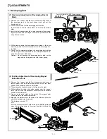

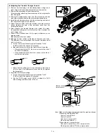


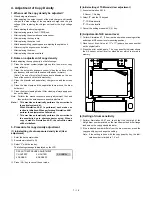


C. Checking the Electrostatic Main Charger Current
The drum current difference(balance) between the sides of front
and rear frame is checked.
1
Perform steps.
2
Clean the saw-tooth plate of the main charger with polystyrene
foam and attach the main charger to the machine.
(Do not attach the transfer/separation charger).
Manually turn on the door switch.
3
Measure the drum current on the sides of front and rear frame.
The difference in current between the front and rear frame must
be 8.0
µ
A or less.
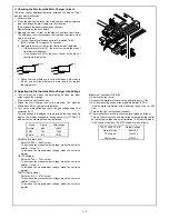
a. Turn on the main switch and perform Simulation "8-02".
(MHVG will be ON for approx. 30 seconds.)
b. Measure the drum current on the front and rear frame side.
•
If the microswitch is OFF, the drum current on the side of
front frame is indicated.
•
If the microswitch if ON, the drum current on the side of
rear frame is indicated.
c. Check that the difference in current between both sides is
8.0
µ
A or less. If the difference is more than 8
µ
A, replace
the charger unit.
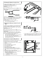
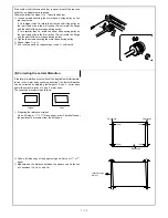
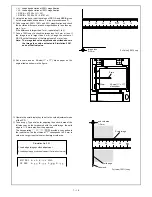
D. Adjusting the Electrostatic Main Charger Grid Voltage
1
Turn off machine. Attach the developing unit and the drum
holder unit to the machine.
(Do not use the electrode sheet).
2
Attach the main charger unit to the machine. The machine
should have all the charger units installed.
3
Turn on the main switch and check the grid voltage using Test
command 44-11.
The grid voltage is displayed in two digits on the copy quantity
display. The display changes in the sequence of N
→
TSM
→
P
mode when the message feed key is pressed.
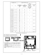
Mode
Figure
Grid voltage
Normal
860
–860V
TSM
755
–755V
Photo
610
–610V
NORMAL (Normal mode)
Set value: 860 = –860V output
To decrease the measurement voltage, make the set value
smaller. (1 step: 1V)
To increase the measurement voltage, make the set value
greater.
T/S (TSM mode)
Set value: 755 = –755V output
To decrease the measurement voltage, make the set value
smaller. (1 step: 1V)
To increase the measurement voltage, make the set value
greater.
PHOTO (Photo mode)
Set value: 610 = –610V output
To decrease the measurement voltage, make the set value
smaller. (1 step: 1V)
To increase the measurement voltage, make the set value
greater.
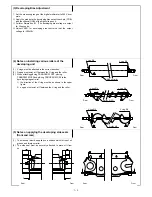
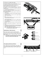
(Measure at check point CP-GB)
4
Remove the rear cover.
5
Connect the digital multimeter to the grid voltage pin (GB).
6
Set the measuring range of the digital multimeter to DCV.
(Use the digital multimeter with measuring range of up to 1000
Vdc).
7
Turn on the front cover switch manually.
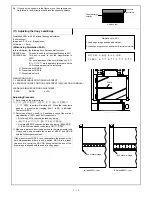
8
There is another method to check the grid votage as follows:
Turn on the main switch, and adjust the output adjusting control
so that output voltage values in Simulation "8-02"(normal mode),
"8-03"(photo mode) and "8-04"(TSM mode) are as follows:
TEST POINT CP-GB
Output Voltage
Normal mode
–860
±
10 V
TSM mode
–755
±
10 V
Photo mode
–610
±
10 V
N/C
N/O COM
(OFF)
N/C
N/O COM
(ON)
7 – 5
Summary of Contents for SF-2040
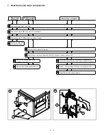
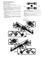
Page 27: ...9 Desk unit SF D23 11 12 16 17 13 18 10 9 8 7 6 2 5 4 3 1 23 21 22 19 20 14 15 4 10 ...
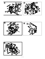
Page 63: ...5 5 C F 10 D 7 6 11 G E 8 9 H 12 6 2 ...
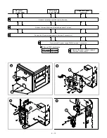
Page 65: ...3 B 3 E 13 C 4 5 6 7 8 F 14 D 10 11 9 6 4 ...
Page 67: ...2 1 3 A D 9 8 11 10 B 4 5 E 12 13 14 C 7 6 6 6 ...
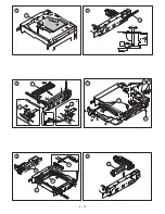
Page 69: ...A a 1 1 D 4 4 B 1 b 1 1 E 5 5 7 6 8 9 8 5 C 2 3 3 F 5 11 12 6 8 ...
Page 71: ...1 2 3 3 4 5 A D 13 11 10 7 6 6 7 B E 14 8 12 9 C F 15 G 16 16 6 10 ...
Page 73: ...A a 1 D 11 10 10 9 8 B 4 2 3 E 13 12 12 C 5 7 6 7 6 12 ...
Page 75: ...C 4 F 9 9 9 10 9 5 6 D G 11 E 8 7 6 14 ...
Page 78: ...Volume PWB 8 9 10 10 6 17 ...
Page 80: ...C 5 F 11 P D F R 7 6 6 12 13 G 12 13 E 8 9 a 8 H 14 6 19 ...