


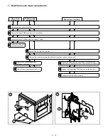
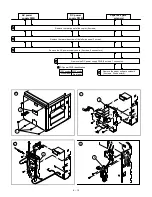


7. Rear frame side major components
1
2
3
4
5
6
7
8
9
10
11
Paper feed
drive unit
Variable paper
speed unit
Main drive unit (belt)
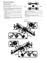
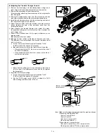
Remove the rear panel (4 screws).
Remove the main PWB connectors (13 connectors).
Remove the main PWB unit from the copier (1 screw).
Remove the paper feed
drive unit (4 screws).
Remove the joint plate (2 screws).
Remove the main drive side pulley holding E-ring, then remove the drive belt.
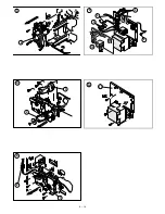
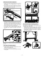
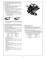
Remove the variable paper feed
speed unit (4 screws).
Remove the variable speed clutch unit.
Unfasten the high voltage unit connectors (6 connectors), and
remove the ground harness from the copier chassis (1 screw each).
Remove the high voltage PWB from the suction duct unit.
Remove the suction unit (6 screws).
1
A
1
2
3
B
6 – 13
Summary of Contents for SF-2040
Page 27: ...9 Desk unit SF D23 11 12 16 17 13 18 10 9 8 7 6 2 5 4 3 1 23 21 22 19 20 14 15 4 10 ...
Page 63: ...5 5 C F 10 D 7 6 11 G E 8 9 H 12 6 2 ...
Page 65: ...3 B 3 E 13 C 4 5 6 7 8 F 14 D 10 11 9 6 4 ...
Page 67: ...2 1 3 A D 9 8 11 10 B 4 5 E 12 13 14 C 7 6 6 6 ...
Page 69: ...A a 1 1 D 4 4 B 1 b 1 1 E 5 5 7 6 8 9 8 5 C 2 3 3 F 5 11 12 6 8 ...
Page 71: ...1 2 3 3 4 5 A D 13 11 10 7 6 6 7 B E 14 8 12 9 C F 15 G 16 16 6 10 ...
Page 73: ...A a 1 D 11 10 10 9 8 B 4 2 3 E 13 12 12 C 5 7 6 7 6 12 ...
Page 75: ...C 4 F 9 9 9 10 9 5 6 D G 11 E 8 7 6 14 ...
Page 78: ...Volume PWB 8 9 10 10 6 17 ...
Page 80: ...C 5 F 11 P D F R 7 6 6 12 13 G 12 13 E 8 9 a 8 H 14 6 19 ...