

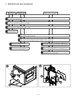


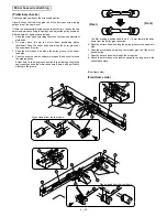

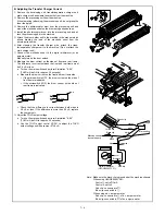


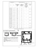

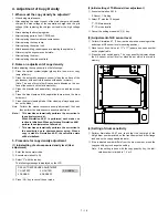


B. Adjusting the Transfer Charger Current
1
Remove the developing unit, transfer/separation charger unit,
main charger unit and waste toner bottle from the machine.
2
Remove the processing unit from the machine.
When removing (attaching) the processing unit, do not grasp the
toner feed pipe.
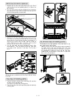
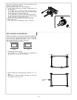
3
Remove the photoreceptor drum from the processing unit and
mount the electrode sheet on the drum using adhesive tape.
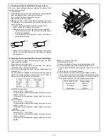
4
Install the photoreceptor drum into the processing unit and at-
tach the processing unit to the machine.
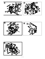
5
Attach the drum holder unit to the machine in the manner which
allows drawing the lead of the electrode sheet from the
developer tank side.
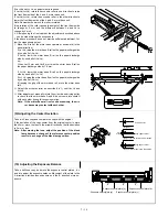
6
After cleaning the transfer charger wire, attach the trans-
fer/separation charger unit to the machine. (Do not attach the
main charger unit).
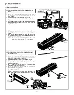
7
Connect the electrode sheet to the digital multimeter (or an
ampere meter).
Manually turn on the door switch.
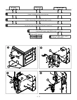
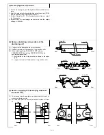
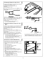
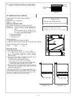
8
Measure the drum current on the sides of front and rear frame.
The difference in current between the front and rear frame must
be 5.0
µ
A or less.
a. Turn on the main switch and perform Simulation "8-06".
(THVG will be ON for approx. 30 seconds)
b. Measure the drum current on the front and rear frame side.
•
If the microswitch is OFF, the drum current on the side of
front frame is indicated.
•
If the microswitch if ON, the drum current on the side of
rear frame is indicated.
c. Check that the difference in current between both sides is
5.0
µ
A or less. If the difference is more than 5.0
µ
A, replace
the charger unit.
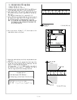
9
Adjust the THVG output voltage:
a. Turn on the main switch and perform Simulation "8-06".
(THVG will be ON for approx. 30 seconds)
b. Use the THVG output control VR201 to adjust the THVG
output voltage until it becomes –57
±
4
µ
A.
Note: Make sure the black clip is grounded at the machine chassis.
When using UKOGE0043CS01:
Control 1: set to DCmA
Control 2: set to 2
Red clip : connected to
⊕
Blue clip: connected to
$
When using a d.c. ampere meter:
Red clip : connected to
$
of d.c. ampere meter
Blue clip: connected to
⊕
of d.c. ampere meter
2
2 0
2 00
(DCmA)
F
R
Green clip
Yellow clip
Black clip
Machine chassis
(uncoated part)
Microswitch
Blue clip
Red clip
Digital multimeter
orange
blue
black
red
orange
white
white
(UKOGE0043FC01)
N/C
N/O COM
(OFF)
N/C
N/O COM
(ON)
7 – 4
Summary of Contents for SF-2040
Page 27: ...9 Desk unit SF D23 11 12 16 17 13 18 10 9 8 7 6 2 5 4 3 1 23 21 22 19 20 14 15 4 10 ...
Page 63: ...5 5 C F 10 D 7 6 11 G E 8 9 H 12 6 2 ...
Page 65: ...3 B 3 E 13 C 4 5 6 7 8 F 14 D 10 11 9 6 4 ...
Page 67: ...2 1 3 A D 9 8 11 10 B 4 5 E 12 13 14 C 7 6 6 6 ...
Page 69: ...A a 1 1 D 4 4 B 1 b 1 1 E 5 5 7 6 8 9 8 5 C 2 3 3 F 5 11 12 6 8 ...
Page 71: ...1 2 3 3 4 5 A D 13 11 10 7 6 6 7 B E 14 8 12 9 C F 15 G 16 16 6 10 ...
Page 73: ...A a 1 D 11 10 10 9 8 B 4 2 3 E 13 12 12 C 5 7 6 7 6 12 ...
Page 75: ...C 4 F 9 9 9 10 9 5 6 D G 11 E 8 7 6 14 ...
Page 78: ...Volume PWB 8 9 10 10 6 17 ...
Page 80: ...C 5 F 11 P D F R 7 6 6 12 13 G 12 13 E 8 9 a 8 H 14 6 19 ...