


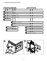


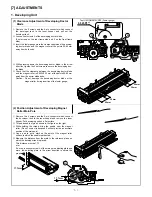

4. Transport baseplate unit
2
3
1
4
5
6
7
8
9
Suction unit transfer belt
Paper stop
roller
Paper stop
clutch
Remove the transport baseplate from the machine
(4 screws on front, 2 on rear, 2 connectors).
Pull the paper entry side rolle towards
the paper exit side, then remove it.
Move the suction transfer belt
to the front side, then remove it.
Remove the DV guide
(6 screws).
Remove the spring and the
auxiliary roller.
Remove the paper stop clutch
(1 screw, and loosen 1 setscrew).
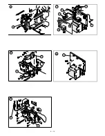
Remove the front side gearwheel (one
each of E-ring, pin, washer, spring).
Remove the bearing
(one each on front and rear).
Remove the paper stop roller.
Suction lift lever
The arrowhead that is shown
on the suction unit transfer belt.
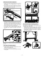
NOTE:
(Remove heater connector
b in Fig. B .)
a in Fig. A and
Loosen screw
shift the suction lift lever to R side,
and the heater unit can be removed.
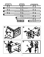
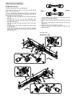
When removing the transport plate unit,
remove the DV tank, the front cabinet,
the process unit, and the upper cassette
(ADU unit) in advance.
Before removing the upper cassette, it is
advisable to remove the paper feed unit
in advance.
Since the fuser unit will serve as the guide
rail for removing and assembling the
transport base plate, do not remove it.
Open the right cabinet.
10 Remove the connecting plate
5 in Fig. F . (2 screws)
11 Remove the stopper and the
22T gear.
12 Remove the P.S clutch
Set screw
Screw
Connector facing downward
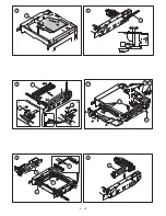
1 Fit the arrow mark in the DV guide with
the groove in the left side of the rail
transport base plate in the multi paper
feed section of the main body and the
mark in the fusing unit cover.
When installing the transport base plate unit
2 Securely engage the transport roller coupling
with the main body coupling. If not, the unit
cannot be inserted fully.
Check that the roller can be turned manually.
(If the couplings are not securely engaged,
the roller cannot be turned manually.)
Coupling
Transport roller
NOTE: Remove the demoisture heater
lamp in the suction section.
6 – 7
Summary of Contents for SF-2040
Page 27: ...9 Desk unit SF D23 11 12 16 17 13 18 10 9 8 7 6 2 5 4 3 1 23 21 22 19 20 14 15 4 10 ...
Page 63: ...5 5 C F 10 D 7 6 11 G E 8 9 H 12 6 2 ...
Page 65: ...3 B 3 E 13 C 4 5 6 7 8 F 14 D 10 11 9 6 4 ...
Page 67: ...2 1 3 A D 9 8 11 10 B 4 5 E 12 13 14 C 7 6 6 6 ...
Page 69: ...A a 1 1 D 4 4 B 1 b 1 1 E 5 5 7 6 8 9 8 5 C 2 3 3 F 5 11 12 6 8 ...
Page 71: ...1 2 3 3 4 5 A D 13 11 10 7 6 6 7 B E 14 8 12 9 C F 15 G 16 16 6 10 ...
Page 73: ...A a 1 D 11 10 10 9 8 B 4 2 3 E 13 12 12 C 5 7 6 7 6 12 ...
Page 75: ...C 4 F 9 9 9 10 9 5 6 D G 11 E 8 7 6 14 ...
Page 78: ...Volume PWB 8 9 10 10 6 17 ...
Page 80: ...C 5 F 11 P D F R 7 6 6 12 13 G 12 13 E 8 9 a 8 H 14 6 19 ...