


MX-2300/2700 N/G ADJUSTMENTS 6 – 60
2)
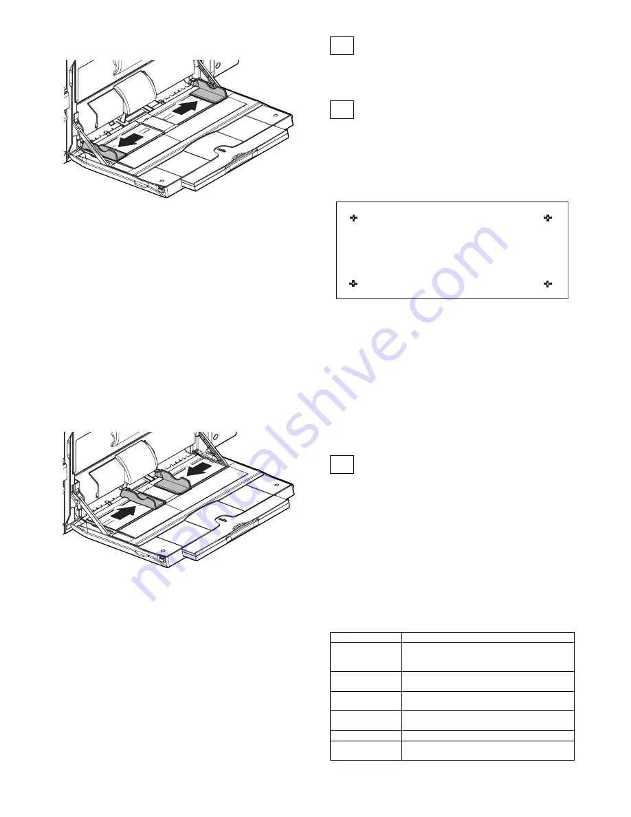
Set the manual paper feed guide to the maximum width posi-
tion.
3)
Press [EXECUTE] key.
[EXECUTE] key is highlighted. Then it returns to the normal
display.
The maximum width position detection level of the manual
paper feed guide is recognized.
4)
Set the manual paper feed guide to the A4 size.
5)
Press [EXECUTE] key.
[EXECUTE] key is highlighted. Then it returns to the normal
display.
The A4 size width position detection level of the manual paper
feed guide is recognized.
6)
Set the manual paper feed guide to the A4R size width.
7)
Press [EXECUTE] key.
[EXECUTE] key is highlighted. Then it returns to the normal
display.
The A4R size width position detection level of the manual
paper feed guide is recognized.
8)
Set the manual paper feed guide to the minimum width posi-
tion.
9)
Press [EXECUTE] key.
[EXECUTE] key is highlighted. Then it returns to the normal
display.
The minimum width position detection level of the manual
paper feed guide is recognized.
If the above operation is not completed normally, "ERROR"
display is highlighted.
When the operation is completed normally, the above data are
saved to the memory and "COMPLETE" is displayed.
25
RSPF tray paper size (width) sensor
adjustment (Refer to the MX-RPX1
SM.)
26
Touch panel coordinate setting
This adjustment is required in the following cases:
* When the operation panel is replaced.
When a U2 trouble occurs.
When the scanner control PWB is replaced.
When the EEPROM on the scanner control PWB is replaced.
1)
Enter the SIM65-1 mode.
2)
Precisely press the cross mark points (4 positions).
When the cross mark is pressed precisely, a buzzer sounds
and the display is reversed. When all the four points are
pressed and the touch panel adjustment is completed, the dis-
play returns to the simulation sub number entry screen.
In case of an error, the display returns to the entry screen
again.
Check to confirm that there is no shift between the display
frame and the detection position when the touch panel is
pressed.
* When pressing the touch panel, never use a sharp tip (such
as a needle or a pin).
27
Image loss, void area, image off-cen-
ter, image magnification ratio auto
adjustment with SIM50-28
The following adjustment items can be executed automatically with
SIM50-28.
* ADJ 8 Print image magnification ratio adjustment (Main scanning
direction) (Print engine section)
* ADJ 9 Image off-center adjustment (Print engine section)
* ADJ 14/15 Scan image magnification ratio adjustment
* ADJ 16 Scan image off-center adjustment
* ADJ 17 Print area (void area) adjustment (Print engine section)
* ADJ 18 Copy image position, image loss adjustment
(Menu in SIM50-28 mode)
Display/Item
Content
OC ADJ
Image loss off-center sub scanning direction image
magnification ratio adjustment (Document table
mode)
BK-MAG ADJ
Main scanning direction image magnification ratio
adjustment
SPF ADJ
Image loss off-center sub scanning direction image
magnification ratio adjustment (RSPF mode)
SETUP/PRINT ADJ
Print lead edge adjustment, image off-center (each
paper feed tray, duplex mode) adjustment
RESULT
Adjustment result display
DATA
Display of data used when an adjustment is
executed