Sharp DM-3551 Operation Manual Download Page 264

5-26

SADDLE STITCH FINISHER

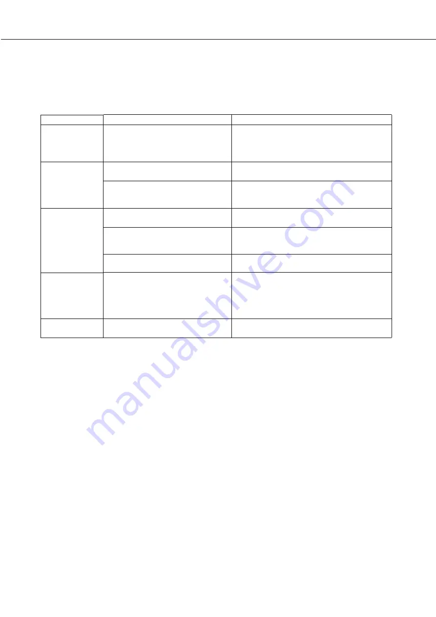
Troubleshooting (concerning the saddle stitch finisher)

Check the list below before calling for service.

Problem

Stapling position
is not correct
(including saddle
stitch).

The saddle stitch
finisher does not
operate.

Stapling cannot
be performed
(including saddle
stitch).

Stapled sets are
not stacked
correctly or some
sheets in a set
are not stapled.

Cannot be
punched.*

Check

Solution or cause

Check the stapling position setting. (See pages
5-27 and 5-28.)

Close all covers. (See page 5-17.)

Remove all remaining paper from the stapler
compiler referring to step 4 on page 5-22.

Remove jammed staples. (See page 5-22.)

Replace the staple cartridge. (See page 5-21.)
Check that a staple cartridge has been installed.
(See page 5-22.)
Stapling cannot be performed onto different size
paper.
Paper may be curled heavily depending on the
paper type and quality. Remove paper from the
paper tray or the bypass tray, turn it upside down,
and load it again.

Dispose of punch scraps. (See page 5-23.)

Stapling position not set properly?

Are any saddle stitch finisher covers
open?
Message indicating need to remove
paper from the stapler compiler
displayed?

Message requesting check for the staple
unit displayed?
Message requesting adding staples
displayed?

Different size paper included?

Paper heavily curled?

Message requesting check for punch
module displayed?

*   When a hole punch module is installed

Summary of Contents for DM-3551

Page 1: ...e to read the installation requirements and cautions sections of the Operation manual for printer operation and general information Be sure to keep all operation manuals handy for reference including this manual the Operation manual for printer operation and general information and operation manuals for any optional equipment which has been installed cover1 p65 4 17 01 9 50 AM 1 ...

Page 2: ...cover1 p65 2 04 01 19 17 2 ...

Page 3: ...on and general information General information required for loading paper adding toner misfeed removal and operation of peripheral devices are described in that manual Separate manuals are provided for the operation of network scanning and facsimile functions Refer to the Operation manual for scanner and Operation manual for facsimile for these descriptions copy 1_Ep P65 2 04 01 19 17 1 ...

Page 4: ...S 15 REDUCTION ENLARGEMENT ZOOM 16 Automatic selection auto image 16 Manual selection 17 SPECIAL PAPERS 18 SPECIAL MODES 19 Common operation procedure for using the special functions 19 Margin shift 20 Erase 21 Dual page copy 22 Pamphlet copy 23 Job build 24 Multi shot 25 JOB PROGRAM MEMORY 26 Storing a job program 26 Recalling a job program 27 Deleting a stored job program 27 INTERRUPTING A PRINT...

Page 5: ... of the originals Document feeder tray page 7 Set the originals here for automatic feeding Operation panel next page Use for operation of copier network scanner and facsimile features and for printer configuration operations Document cover Document scanning windows Sheet type originals are scanned here Document glass All originals which cannot be copied from the document feeder tray must be copied...

Page 6: ...t the number of copies and to make numerical entries for setting operations C key clear key Press to clear a copy quantity entry If this key is pressed while the automatic document feeder is being used any originals in progress will be automatically output CA key clear all key Press to clear all selected settings and return the machine to the initial settings for the currently selected mode Before...

Page 7: ... key are described on page 19 Paper size display The display shows the location of the paper trays the size of the paper in the trays and the approximate amount of paper loaded in each tray The approximate amount of paper in a tray is indicated by For changing the paper size in a tray refer to page 1 16 of the Operation manual for printer operation and general information Original size display The...

Page 8: ...r clips If originals have damp spots from correction fluid ink or glue from pasteups be sure they are dried before they are fed If not the interior of the document feeder or the document glass may be soiled To prevent incorrect original size detection original misfeeds or smudges on copies use the following as a guide for feeding originals Transparency film tracing paper carbon paper thermal paper...

Page 9: ...e tip of the scale mark at the left rear corner of the glass as shown in the illustrations When using the automatic document feeder 1 Ensure that there is no original on the document glass 2 Adjust the original guides to the size of the originals 3 Place the originals face down in the document feeder tray Set the originals all the way into the feed slot Do not exceed the maximum height line marked...

Page 10: ...er than 8 1 2 x 11 or A4 is selected rotation cannot be done Example This function operates in the auto paper select or auto image mode Rotation copying can be disabled with a key operator program See page 33 Orientation of original Orientation of paper Copy after rotation Face down Face down Place originals in the document feeder tray or on the document glass so that the top of the original is po...

Page 11: ...be highlighted 5 Touch the OK key OK 0 6 Ensure that paper of the same size as the originals is automatically selected Note COPY RATIO AUTO PAPER SELECT 100 81 2 11 X The selected tray will be highlighted or the message LOAD xxxxxx PAPER will appear If the message ap pears load paper in a pa per tray or the bypass tray with paper of the required size Even if the message above is displayed copy ing...

Page 12: ... number of copies Up to 999 can be set Use the C clear key to cancel an entry if a mistake has been made 9 Press the START key If the C key is pressed while originals are being scanned scanning will stop If copying had already started copying and scanning will stop after the original in progress is output to the original exit area In these cases the copy quantity will be reset to 0 If scanning has...

Page 13: ...in the document feeder tray page 7 2 Touch the 2 SIDED COPY key 2 SIDED COPY OUTPUT 3 Select the desired duplex copy mode BIN CH The illustration to the left shows the screen displayed when a duplex module is installed Original Copy NORMAL COPYING 4 Touch the OK key BINDING CHANGE OK Follow step 6 on page 9 to step 9 on page 10 The image to be copied onto the second side of 2 sided copies can be i...

Page 14: ... are not needed 3 Ensure that paper of the same size as the original is automatically selected Note COPY RATIO AUTO PAPER SELECT 100 81 2 11 X The selected tray will be highlighted or the message LOAD xxxxxx PAPER will appear If the message appears load paper in a paper tray or the bypass tray with paper of the required size Even if the message above is displayed copying can be performed onto the ...

Page 15: ...ced in the document feeder tray a sort icon will appear on the touch panel and the sort copy mode will be automatically selected In this case copies will be delivered as shown in the upper illustration to the left For output in the group mode as shown in the lower left illustration the group mode must be selected on the output setting screen Output mode sort copy and group copy Example Five sets o...

Page 16: ...he 2 SIDED COPY key 2 SIDED COPY OUTPUT 3 Touch the 1 sided to 2 sided copy key Original Copy NORMAL COPYING The image to be copied onto the second side of 2 sided copies can be inverted so that the resultant 2 sided copies are in the correct orientation for binding at the top For top binding touch the BINDING CHANGE key on the 2 sided copy selection screen 4 Touch the OK key BINDING CHANGE OK Fol...

Page 17: ...l to be copied PHOTO TEXT TEXT PHOTO NOTE Exposure mode selection TEXT This mode is useful for producing dark text copies with minimum background TEXT PHOTO This provides the best balance for copying an original which contains both text and photos This mode is also useful for copying printed photographs PHOTO This mode provides the best copies of photographs with fine details 3 Adjust the exposure...

Page 18: ...in the AB system 2 Touch the PAPER SELECT key and then select the desired paper size TRANSPA 81 2 11 X 81 2 11 X 11 17 x 1 2 3 PLAIN PLAIN When the desired paper size key is touched the paper size will be highlighted and the paper size setting window will be closed If paper of the desired size is not loaded in any tray load paper of the required size in a paper tray and enter the paper size 3 Touc...

Page 19: ... 14 x 11 17 x 81 2 11 x 11 17 x 81 2 14 x 81 2 11 x 81 2 14 x 81 2 11 x 51 2 81 2 x 51 2 81 2 x If the message IMAGE IS LARGERTHANTHE COPY PAPER appears image loss will occur In this case either continue with image loss or change the copy paper size or copy ratio 4 Ensure that the desired paper size has been automatically selected based on the selected copy ratio or select another size as needed P...

Page 20: ...ss page 7 2 Load the special paper in the bypass tray or in the multi purpose drawer For the paper loading instructions see Loading paper in the bypass tray page 5 3 of the Operation manual for printer operation and general information or Loading paper in the multi purpose drawer page 1 21 of the Operation manual for printer operation and general information 3 Touch the PAPER SELECT key and then s...

Page 21: ...r modes requiring setting screens start on the next page The dual page copy and job build functions do not require setting screens MARGIN SHIFT SPECIAL MODES PAMPHLET COPY ERASE JOB BUILD MULTI SHOT DUAL PAGE COPY OK Margin shift page 20 Erase page 21 Dual page copy page 22 Pamphlet copy page 23 Job build page 24 Multi shot page 25 When using the multi shot function set the original select the des...

Page 22: ...ted to the right Image shifted to the left Original Image shifted to the right Image shifted to the left Margin Margin or Margin Margin 3 Set the shift amount as needed and touch the OK key inch 1 2 0 1 SIDE 2 OK OK CANCEL SIDE 1 inch 3 8 0 1 Use the key and the keys to set the shift amount The shift amount can be set from 0 to 1 in 1 8 increments 0 mm to 20 mm in 1 mm increments for the AB system...

Page 23: ...s and eliminates the shadow at the center of copies 1 Touch the ERASE key on the SPECIAL MODES screen JOB BUILD ERASE The erase setting screen will appear 2 Select the desired erase mode ERASE EDGE ERASE CENTER ERASE EDGE CENTER ERASE Select one of the three erase modes The selected key will be highlighted 3 Adjust the amount of erase and touch the OK key inch 1 2 0 1 EDGE CANCEL OK Use the and ke...

Page 24: ...on the document glass Center line of original Index This page is copied first 81 2 x11 or A4 Dual page copy Book original When copying book originals When copying a thick book press down lightly on the document cover 4 Ensure that 8 1 2 x 11 or A4 size paper is selected COPY RATIO PAPER SELECT AUTO 100 81 2 11 x If 8 1 2 x 11 or A4 size paper is not selected touch the PAPER SELECT key to select 8 ...

Page 25: ...ill be selected automatically based on the original size and the paper size See steps 2 and 3 on page 16 7 Make all other desired settings such as exposure or the number of copies and press the START key 8 When using the automatic document feeder Copying will start after all originals have been scanned The next step is not needed When using the document glass Replace the original with the next ori...

Page 26: ...D key will be highlighted 2 Touch the OK key on the special modes screen while JOB BUILD is highlighted OK ERASE JOB BUILD DUAL PAGE COPY MULTI SHOT 3 Place the first section originals in the document feeder tray page 7 Originals Page 1 50 sheets Page 51 50 sheets Divide the originals in sections of 50 sheets and scan the originals starting from the first page of section A and then scan section B ...

Page 27: ...ch the MULTI SHOT key on the SPECIAL MODES screen MULTI SHOT The multi shot setting screen will appear 2 Select the number of originals to be copied onto one sheet of copy paper on the multi shot selection screen 2in1 4in1 The orientation of copy paper and the image of the originals may be rotated as needed 3 Select the layout LAYOUT Select the order in which the originals will be arranged on the ...

Page 28: ...y from 1 to 10 on the storage register screen 1 6 RECALL ESS PROGRAM NUMBER PROGRAMS STORE 2 3 4 7 8 9 Highlighted storage register numbers are registers which already have programs stored If a highlighted number is selected a screen will appear with selections for deleting the selected program storing replacing the selected program with a new one or canceling to go back to the STORE DELETE screen...

Page 29: ...rogram to be deleted 5 10 3 8 4 9 EXIT STORE DELETE If a number key for which no job program has been stored is selected the screen will change to the screen of step 4 on the previous page for storing a program The message TO STORE SELECT AND PRESS OK TO DELETE PRESS CANCEL will appear When CANCEL is pressed the screen will return to the selection screen shown to the left 3 Touch the DELETE key RE...

Page 30: ... will appear as shown in the illustration CANCEL 0 AUTO TO 100 81 2 11 X EXPOSURE PER SELECT ORIGINAL 81 2 11 X When the INTERRUPT key is touched in step 2 the INTERRUPT touch key will be replaced by the CANCEL key as shown in the illustration To cancel interrupt copying at any time touch the CANCEL key 3 Make all other desired settings such as exposure paper size and number of copies and then pre...

Page 31: ...splayed on the touch panel 1 Open the document feeding area cover and remove any misfed originals Document feeding area cover 2 Close the document feeding area cover Close the cover securely so that cover clicks into place 3 Open the document cover and turn the green rotating knob in the direction of the arrow to remove any misfed originals 4 Close the document cover A message may appear indicatin...

Page 32: ...rder of originals correct Is a message requesting cancelation of job displayed Is a message indicating memory is full displayed Check Solution or cause If the indicator is not on the machine may be warming up Warm up should be completed in approximately 80 seconds Adjust the exposure in the manual mode See page 15 The exposure level in the AUTO mode can be adjusted using a key operator program Con...

Page 33: ...nal feed system Automatic continuous feeding Original exit system Face down output Original transport system DSPF sheet through type reference position center document glass reference position is left rear Original setting direction Face down Original sizes 5 1 2 x 8 1 2 to 11 x 17 or A5 to A3 Original weight 14 to 34 lbs or 50 to 128 g m2 Capacity Up to 50 sheets 30 sheets 1 for 8 1 2 x 14 or B4 ...

Page 34: ...status settings 33 Exposure adjustment 33 Rotation copy setting 33 Auto paper selection setting 33 600dpi x 600dpi scanning mode 33 Quick scan from document glass 33 Device control Original size detector setting 34 Disabling of document feeder 34 Using the key operator programs To use of the key operator programs follow the procedures described in the Key Operator s Guide on page 6 Also read Suppl...

Page 35: ...9 indicates darker density on the touch panel Rotation copy setting If this program is set the image of originals will rotate when the orientation of the originals does not match that of the copy paper Rotation copy will function only if the auto paper select or auto image mode has been selected NOTE For copying from 5 1 2 x 8 1 2 or A5 size originals onto 5 1 2 x 8 1 2R or A5R paper this program ...

Page 36: ...nd no original size will be displayed Disabling of document feeder This program is used to prevent use of the automatic document feeder when the scanner module malfunctions In this case scanning can still be done off the document glass KEY OPERATOR PROGRAMS Detectable original sizes Group Documentfeedertray forautomaticdocumentfeeding Document glass 11 x 17 8 1 2 x 14 1 INCH 1 8 1 2 x 11 8 1 2 x 1...

Page 37: ...cover4 p65 2 04 01 19 18 1 ...

Page 38: ...INSE2077FCZZ Operation manual for copier PRINTED IN CHINA SHARP ELECTRONICS CORPORATION Sharp Plaza Mahwah New Jersey 07430 2135 SHARP CORPORATION P350 P450 3500 3501 3551 4500 4501 4551 cover4 p65 2 04 01 19 18 2 ...

Page 39: ...this product be sure to read the installation requirements and cautions sections of the Operation manual for printer operation and general information Be sure to keep all operation manuals handy for reference including this manual the Operation manual for printer operation and general information and operation manuals for any optional equipment which has been installed ...

Page 40: ......

Page 41: ...t be established by the network administrator Such settings must be effected by the system administrator who has the special network related backgrounds This manual assumes that several options have been installed TABLE OF CONTENTS Page INTRODUCTION 1 SETTINGS AND PROGRAMMING REQUIRED FOR THE NETWORK SCANNER FEATURE 2 ABOUT THE WEB PAGE 2 SETTING PASSWORDS 2 BASIC SETTINGS FOR NETWORK SCANNING 3 S...

Page 42: ...DS Passwords can be set to restrict Web page access and protect settings Note that it is not necessary to set passwords the network scanner functionality can also be used without passwords A password can be set for the administrator and passwords can be set for each user If you use a user password to access theWeb page you will be able to establish edit and delete destinations in the Scanner Desti...

Page 43: ...ct only used for Scan to E mail Enter a subject when using Scan to E mail Only one subject can be entered If nothing is entered Scanned image from Device Name will appear The name that appears in Device Name is the name stored in Name in the screen that appears when you click Status Alert E mail in the menu frame If a name has not been stored the product name will appear E mail Server and DNS Serv...

Page 44: ...must also click E mail and then enter the settings under E mail Setup for the e mail server Refer to page 3 Storing destinations for Scan to Desktop Scan to Desktop can only be used if Network Scanner Tool is installed in your computer Network Scanner Tool is included on the CD ROM that accompanies the AR NS2 Network Scanner Expansion Kit You can store a Scan to Desktop destination in the Web page...

Page 45: ...e so you only need to make a selection if the initial settings are not satisfactory For an explanation of the initial settings of each of the transmission methods click Help in the menu frame NOTE Internet Fax only has one file format TIFF F and thus there is no selection MH G3 or MMR G4 can be selected for the compression mode STORING SENDER INFORMATION To store the sender information Sender Name...

Page 46: ...ss Directory screen next page Touch this key when you want to use an auto dial number one touch dialing or group dialing ADDRESS REVIEW key page 10 When performing Scan to E mail or Internet Fax broadcast transmission touch this key to check your selected destinations Your selected destinations will appear as a list and the list can be edited SENDER LIST key page 8 Touch this key to select the sen...

Page 47: ... the screens NOTE The screen showed above is the alphabetical address directory If desired the initial screen can be set to the group address directory refer to page 26 CONDITION SETTINGS key This displays the condition setting screen previous page which is used to set various conditions ABC GROUP key Touch this key to switch between the alphabetical index and the group index Index keys One touch ...

Page 48: ...ed adjust the resolution setting Refer to page 13 AUTO 8 X11 ORIGINAL STANDARD RESOLUTION PROGRAMMED FILE FORMAT 1 2 The initial factory setting is STANDARD 5 If needed adjust the exposure setting Refer to page 14 AUTO 8 X11 AUTO EXPOSURE STANDARD RESOLUTION PROGRAMMED FILE FORMAT 1 2 The initial factory setting is AUTO 6 If needed select the file format Refer to page 15 AUTO 8 X11 ORIGINAL STANDA...

Page 49: ...y ends and the transmission job is stored 14After the final page is scanned touch the READ END key READ END L Pg No 3 ESS READ END The machine makes a beep sound to inform you that the transmission job is stored and JOB STORED appears in the message display The destination is automatically called and the document transmitted after previously stored jobs are completed Open the document glass cover ...

Page 50: ...ey RESSION MODE CANCEL OK OK You will return to the initial screen If you are not performing a broadcast transmission go directly to step 9 7 If you wish to enter another e mail address repeat steps 2 through 6 NOTES If the key operator program has been set so that the NEXT ADDRESS key must always be pressed page 26 and you wish to enter another address press the NEXT ADDRESS key and then repeat s...

Page 51: ...ent in the auto document feeder 2 Touch the ORIGINAL key AUTO 8 X11 ORIGINAL RESOLUTION PROGRAMMED FILE FORMAT 1 2 When you touch the ORIGINAL key check the original size displayed in the key 3 Touch the 2 SIDED BOOKLET key or the 2 SIDED TABLET key as appropriate for the original you loaded AUTO MANUAL 2 SIDED BOOKLET 2 SIDED TABLET ORIGINAL SIZE If necessary touch the MANUAL key and set the orig...

Page 52: ...1 2 2 Touch the MANUAL key ROTATE THE IMAGE 90 DEGREE MANUAL ST UTO 2 SIDED TABLET 2 SIDED BOOKLET ORIGINAL SIZE The sizes that can be selected are displayed NOTE If you wish to rotate the original 90 when creating an image file click the Load the original so that the image is oriented horizontally checkbox a checkmark should appear in the box 3 Touch the desired original size key OK OK INCH AB OR...

Page 53: ...e initial screen NOTES The initial factory resolution setting is Standard If desired you can change the initial setting to a different setting using the key operator program Refer to page 26 When using the automatic document feeder the resolution setting cannot be changed once scanning has begun Resolution settings Standard Touch this key if your original consists of normal sized characters like t...

Page 54: ... key 2 Touch the desired exposure key AUTO DARK ORIGINAL LIGHT ORIGINAL The selected key is highlighted 3 Touch the OK key OK LIGHT You will return to the initial screen NOTE When using the document glass to scan pages an original the exposure setting can be changed each time you change pages When using the automatic document feeder the exposure setting cannot be changed once scanning has begun Da...

Page 55: ...IFF TIFF F PDF MH G3 MMR G4 PROGRAMMED PROGRAMMED NONE FILE TYPE COMPRESSION MODE OK NOTE When the ONE PAGE PER FILE checkbox is not selected all scanned pages are combined into a single file When the checkbox is selected one file is created per page 3 Touch the OK key MH G3 MMR G4 ED PROGRAMMED NONE COMPRESSION MODE OK You will return to the initial screen NOTES The initial file format setting ca...

Page 56: ...ON OF A STORED JOB If you have an urgent transmission job and multiple transmission jobs have already been stored you can give priority to the urgent job so that it will be transmitted immediately after the job currently being executed This is done from the job status screen For details on using the job status screen refer to page 1 14 of Operation manual for printer operation and general informat...

Page 57: ...X E MAIL INTER The No that automatically appears is the lowest number from 001 to 500 that has not yet been programmed When NAME is touched the letter entryscreenappears Enterup to 36 characters for the name NOTE If you are going to use the Web page to edit or delete the stored name at a later time do not use the characters or These characters cannot be displayed in theWeb page 7 Touch the INITIAL...

Page 58: ...the key Only the first 18 characters of the name entered in step 6 will be displayed If you need to change the name that will be displayed in the key touch the KEY NAME key NAME SHARP CORPORATION E MAIL INTERNET REGISTRATION IS COMPLETED INDEX USER 3 ADDRES KEY NAME SHARP CORPORATION If you do not wish to change the name this step is not necessary 17Check the file format and the compression mode F...

Page 59: ...PDF MMR G4 FILE FORMAT INTERNET FAX 5 Make sure that your changes are correct and then touch the EXIT key S INITIAL DELETE EXIT If you wish to change another one touch key repeat steps 3 through 5 6 Touch the DELETE key S INITIAL DELETE EXIT 7 Touch theYES key DELETE THE ADDRESS SHARP CORPORATION NO YES SHARP CORPORATION PDF FILE FORMAT If you wish to delete another one touch key repeat steps 3 6 ...

Page 60: ...t of your selected destinations is displayed You can delete a displayed destination by touching it When a message appears asking if you want to delete the destination touch the YES key 7 Touch the outer OK key DIRECT ADDRESS GROUP SELECT ADDRESS TO DELETE GROUP NAME SHARP GROUP OK OK SHARP CORPORATION TPS The number of destinations in the group appears to the right of the ADDRESS key 8 Check the n...

Page 61: ...P A B C GROUP SHARP CORPORATION TPS The one touch keys stored in the group are highlighted To add another one touch key to the group touch the key to highlight it To delete a one touch key from the group touch the key so that it is no longer highlighted 5 Make sure the edited information is correct and then touch the EXIT key S INITIAL DELETE EXIT ES If you wish to change another group key repeat ...

Page 62: ...E ADDRESS SENDER NAME 1 GROUP The display changes to the address entry screen when you touch the RE ADDRESS key Up to 64 characters can be entered for the sender s e mail address When finished press the OK key to return to the original screen 6 If you have finished storing senders touch the EXIT key If you wish to store another sender touch the NEXT key EDITING AND DELETING SENDER INFORMATION Use ...

Page 63: ...dex key USER 1 to USER 6 You can enter a name for the selected index CUSTOM SETTINGS CUSTOM INDEX SELECT THE KEY TO BE CUSTOM NAMED OK USER 1 USER 2 USER 3 USER 4 USER 5 USER 6 When touched the letter entry screen appears 4 Enter a maximum of 6 characters for the index name Use the key to clear the displayed name and then enter the desired name When finished touch the OK key The new name appears i...

Page 64: ...ou send a scanned image a message informing you of the error and an error code will appear in the touch panel on the machine Error Code Table Error Code Description of the Error CE 01 The optional network interface card Print Server Card is not installed or is out of order CE 02 Cannot find the specified mail server or FTP server CE 03 The server was down during the scanning of the original CE 04 ...

Page 65: ...M LIST Program name Page Image send settings Operation settings Default display setting 26 The number of direct address keys displayed setting 26 Must input next address key at broadcast setting 26 Initial resolution setting 26 Scan to E mail initial status settings Default sender set 27 Initial file format setting 27 Compression mode at broadcasting 27 USING THE KEY OPERATOR PROGRAMS To use a key...

Page 66: ...a maximum of 18 characters can appear when the number of one touch keys displayed is set to 6 or 8 A maximum of 10 characters can appear when the number of one touch keys displayed is set to 12 Must input next address key at broadcast setting You can select whether the NEXT ADDRESS key must be pressed before entering the next destination when performing a broadcast transmission only for Scan to E ...

Page 67: ...ssion mode at broadcasting Default sender set If you do not select a sender when performing a Scan to E mail operation the sender information stored with this setting is automatically used You can check the stored sender information by printing the SENDER list 1 Touch the SENDER NAME key and then enter the sender name The sender name entry screen appears Up to 20 characters can be entered 2 Touch ...

Page 68: ... 10Base T 100Base TX Supported mail system Mail servers supporting SMTP Number of destinations 500 maximum 2 Number of senders 20 maximum Output resolution Destination type E mail FTP Broadcast transmission Broadcast transmission Resolution E mail Internet Fax Fax E mail Internet Fax STANDARD 200x200dpi 200x100dpi 203 2x97 8dpi 8x3 85line mm FINE 300x300dpi 200x200dpi 203 2x195 6dpi 8x7 7line mm S...

Page 69: ......

Page 70: ...Operation manual for network scanner SHARP CORPORATION PRINTED IN CHINA 2002D KS1 TINSE2292FCZZ ...

Page 71: ...ctions of the Operation manual for printer operation and general information Be sure to keep all operation manuals handy for reference including this manual the Operation manual for printer operation and general information and operation manuals for any optional equipment which has been installed 350LP 450LP 350M 450M 3500 3501 3551 4500 4501 4551 Operation manual for facsimile SHARP CORPORATION P...

Page 72: ...ed and found to comply with the limits for a Class A digital device pursuant to part 15 of the FCC Rules These limits are designed to provide reasonable protection against harmful interference when the equipment is operated in a commercial environment This equipment generates uses and can radiate radio frequency energy and if not installed and used in accordance with the instruction manual may cau...

Page 73: ...please consult your dealer or your nearest Sharp customer assistance center When the lithium battery dies a message will appear in the display and the unit will no longer function Other information If a thunderstorm occurs we recommend that you unplug the power cord from the power outlet Information will be retained in memory even if the power cord is unplugged INTRODUCTION Thank you for purchasin...

Page 74: ...ORED JOB 2 6 CANCELING A FAX TRANSMISSION 2 6 RECEIVING FAXES 2 7 RECEIVING A FAX 2 7 CHAPTER 3 USINGCONVENIENTFUNCTIONS1 ADVANCED TRANSMISSION METHODS Page SENDING THE SAME DOCUMENT TO MULTIPLE DESTINATIONS IN A SINGLE OPERATION BROADCAST TRANSMISSION 3 2 USING BROADCAST TRANSMISSION 3 3 AUTOMATIC TRANSMISSION AT A SPECIFIED TIME TIMER TRANSMISSION 3 4 SETTING UP A TIMER TRANSMISSION 3 4 TRANSMIS...

Page 75: ...S AND PROGRAMS 6 2 STORING ONE TOUCH DIAL KEYS 6 3 EDITING AND DELETING ONE TOUCH KEYS 6 5 PROGRAMMING A GROUP KEY 6 6 EDITING AND DELETING GROUP KEYS 6 7 STORING A PROGRAM 6 8 EDITING AND DELETING PROGRAMS 6 8 Page STORING A GROUP INDEX 6 9 PROGRAMMING EDITING AND DELETING F CODE MEMORY BOXES 6 10 PROGRAMMING AN F CODE MEMORY BOX 6 10 SETTING FOR F CODE POLLING MEMORY BOXES NUMBER OF TRANSMISSION...

Page 76: ...ervice temporarily If possible They will notify you in advance If advance notice is not practical you will be notified as soon as possible You will also be advised of your right to file a complaint with the FCC Your telephone company may make changes in its facilities equipment operations or procedures that could affect the operation of your equipment If this happens the telephone company will pro...

Page 77: ...TANT SAFETY INFORMATION If any of your telephone equipment is not operating properly you should immediately remove it from your telephone line as it may cause harm to the telephone network The AC power outlet shall be installed near the equipment and shall be easily accessible Never install telephone wiring during a lightning storm Never install telephone jacks in wet locations unless the jack is ...

Page 78: ...S AU CANADA AVIS L étiquette de l Industrie Canada identifie le matériel homologué Cette étiquette certifie que le matériel est conforme à certaines normes de protection d exploitation et de sécurité des réseaux de télécommunications Industrie Canada n assure toutefois pas que le matériel fonctionnera à la satisfaction de l utilisateur Avant d installer ce matériel l utilisateur doit s assurer qu ...

Page 79: ...LATION 1 2 A LOOK AT THE OPERATION PANEL 1 3 FAX MODE CONDITION SETTING SCREEN 1 4 ORIGINALS 1 6 ORIGINALS THAT CAN BE FAXED 1 6 LOADING A DOCUMENT 1 7 USING THE AUTO DOCUMENT FEEDER 1 7 USING THE DOCUMENT GLASS 1 7 CHECKING THE SIZE OF A LOADED ORIGINAL 1 8 MANUALLY SETTING THE SCANNING SIZE 1 8 SELECTING RESOLUTION AND EXPOSURE SETTINGS 1 9 SELECTING THE RESOLUTION 1 9 SELECTING THE EXPOSURE 1 1...

Page 80: ...mmed in the unit refer to page 3 15 of Operation manual for printer operation and general information If the date and time are wrong please correct them It is important to set the correct date and time because they are used for such features as Timer Transmission page 3 4 Program the sender s name and sender s number Refer to page 8 4 to program the name and fax number of the user of this product ...

Page 81: ...ub addresses passcodes and numerical settings One digit is cleared each time you press the key When an original is being scanned this key can also be used to cancel scanning CA key Use to cancel a transmission or programming operation When the key is pressed the operation is canceled and you return to the initial screen next page When sending a fax this key is also used to cancel an image setting ...

Page 82: ...an auto dial number one touch dialing or group dialing SUB ADDRESS key page 4 3 Touch this key to enter a sub address or passcode ADDRESS REVIEW key When performing a broadcast transmission touch this key to check your selected destinations Your selected destinations will appear as a list and the list can be edited Two sided scanning and verification stamp icon display pages 2 5 and 5 2 Icons appe...

Page 83: ...stom settings refer to pages 6 3 and 6 9 Frequently used one touch key destinations can be stored on the FREQUENT USE card for convenient access One touch key display This shows the one touch keys that have been stored on the selected index card The key type is indicated by the icon at the right One touch keys in which a fax number is stored are indicated by a icon The display is initially set to ...

Page 84: ...cannot be scanned Far edge Near edge Bottom edge Top edge Area that cannot be scanned 0 2 or less at top edge and 0 2 or less at bottom edge Near edge far edge 0 2 or less Faxed document width Receiving machine s paper width Reduced size Ratio 11 x17 8 1 2 x14 8 1 2 x14 1 0 64 Area ratio 11 x17 8 1 2 x11 8 1 2 x11 R 1 0 5 Area ratio 8 1 2 x14 8 1 2 x11 8 1 2 x11 R 1 0 78 Area ratio A document can ...

Page 85: ...Do not place any objects under the original size detector plate Closing the document glass cover with an object underneath may damage the original size detector plate and prevent correct detection of the document size 3 Align the edges of the document pages and then insert the stack in the document feeder so that the first page is face down Insert the stack into the auto document feeder until it s...

Page 86: ...nce again 4 Touch the outer OK key REDIAL OK OK KER L A4 You will return to the initial screen Pressing the inner OK key in the step above returns you to step 2 5 The selected size appears in the top half of the ORIGINAL key ORIGINAL STANDARD RESOLUTION A4 If you loaded a long original If you loaded a long up to 31 5 original in the auto document feeder touch the LONG SIZE key in step 3 above NOTE...

Page 87: ...ator program Refer to page 8 3 When using the automatic document feeder the resolution setting cannot be changed once scanning has begun Even if you send a document using Fine Super fine or Ultra fine resolution some receiving fax machines may not be able to print the document at the same resolution Resolution settings Standard Touch this key if your original consists of normal sized characters li...

Page 88: ...Touch the outer OK key OK OK LIGHT You will return to the initial screen Dark Select this setting if your original consists Original mostly of dark characters Auto This setting automatically adjusts the ex posure for light and dark parts of the origi nal Light Select this setting if your original consists Original mostly of faint characters Exposure settings NOTE When using the document glass to s...

Page 89: ...ber On hook dialing This feature allows you to dial without lifting an extension phone connected to the machine Press the SPEAKER key listen for the dial tone through the speaker and then dial To speak with another person you must lift the extension phone connected to the machine when they answer Faxes must be sent manually when using on hook dialing Refer to page 5 3 On hook dialing is not possib...

Page 90: ......

Page 91: ...s such as sending faxes Page SENDING A FAX 2 2 BASIC PROCEDURE FOR SENDING FAXES 2 2 TRANSMISSION BY AUTO DIALING 2 5 TRANSMITTING A TWO SIDED DOCUMENT 2 5 PRIORITY TRANSMISSION OF A STORED JOB 2 6 CANCELING A FAX TRANSMISSION 2 6 RECEIVING FAXES 2 7 RECEIVING A FAX 2 7 ...

Page 92: ...et the document size Refer to page 1 8 4 If needed adjust the resolution setting Refer to page 1 9 AUTO 8 X11 1 2 ORIGINAL STANDARD RESOLUTION 5 If needed adjust the exposure setting Refer to page 1 10 POLLING EXPOSURE DUAL PAGE SCAN SPECIAL MODES SRANDARD RESOLUTION 6 Dial the fax number The number that you entered appears in the message display If it is not correct press the C key and re enter t...

Page 93: ... the job as explained on page 2 6 If the machine makes two beeps during or at the end of transmission and an error message appears in the message display refer to page 7 3 to fix the problem If the power is turned off or a power failure occurs while a document is being scanned in the auto document feeder the machine will stop and a document jam will occur After power is restored remove the documen...

Page 94: ... send only the pages already scanned by touching the SEND key The page that was being scanned when the memory became full will be cleared from memory If the memory becomes full while scanning the first page of a document the transmission job is automatically canceled The number of jobs that can be stored will depend on the number of pages in each job and the transmission conditions The number of s...

Page 95: ...to dialing one touch dialing or group dialing instead of entering a full fax number with the numeric keys follow the steps below To use an auto dial destination you must first program the full fax number and name of the destination Refer to page 1 11 for information on auto dialing and pages 6 3 6 6 for information on programming auto dial destinations 1 Perform steps 1 through 5 of Basic Procedur...

Page 96: ...ve an urgent transmission job and multiple transmission jobs have already been stored you can give priority to the urgent job so that it will be transmitted immediately after the job currently being executed This is done from the job status screen For details on using the job status screen refer to page 1 14 of Operation manual for printer operation and general information 1 Press the JOB STATUS k...

Page 97: ...o talk with the other person If received data cannot be printed If the machine runs out of paper or toner or a paper jam occurs print and copy jobs that are in progress will be held in memory until printing becomes possible The jobs are automatically printed when printing capability is restored When received data is held in memory the DATA light next to the IMAGE SEND key blinks You can also use t...

Page 98: ......

Page 99: ...3 2 USING BROADCAST TRANSMISSION 3 3 AUTOMATIC TRANSMISSION AT A SPECIFIED TIME TIMER TRANSMISSION 3 4 SETTING UP A TIMER TRANSMISSION 3 4 TRANSMISSION AND RECEPTION USING THE POLLING FUNCTION 3 5 USING THE POLLING FUNCTION 3 6 USING POLLING MEMORY 3 7 OWN NUMBER SENDING 3 9 FAXING A DIVIDED ORIGINAL DUAL PAGE SCAN 3 10 PROGRAMMING FREQUENTLY USED OPERATIONS 3 11 USING A PROGRAM 3 11 TRANSFERRING ...

Page 100: ...ents to the same group of destinations it is convenient to program those destinations into a group key A group key is a one touch key in which multiple destinations are programmed The procedure for programming group keys is explained on page 6 6 When using a group key to send a fax the destinations programmed in the group key are counted as broadcasting destinations For example if five destination...

Page 101: ... when successively dialing fax numbers with the numeric keys Example XXXX NEXT ADDRESS XXXX Dial Dial Cannot be omitted XXXX NEXT ADDRESS One touch NEXT ADDRESS One touch Dial Can be omitted Can be omitted If desired you can use the key operator program to set the machine so that the NEXT ADDRESS key must always be pressed refer to page 8 3 4 Touch the ADDRESS REVIEW key to display the list of des...

Page 102: ...t the day of the week Touch the key or the key until the desired day is selected DAY OF THE WEEK IMER The initial setting is no selection If you select this setting the transmission will be performed as soon as the specified time arrives SETTING UP A TIMER TRANSMISSION 4 Select the time Touch the key or the key until the desired time appears 30 CANCEL TIME HH mm Select the time in 24 hour format E...

Page 103: ...ion allows your machine to call a sending machine and initiate reception of a document loaded in that machine A timer setting can also be established to have the operation take place at night or another specified time refer to the previous page The other machine Document data previously scanned into memory Your machine Polling ask other machine to send document Document data is automatically sent ...

Page 104: ...orming serial polling an auto dial key that includes a sub address or passcode page 4 2 cannot be selected 4 When you have finished entering the destination s press the START key JOB STORED appears in the screen Your machine prints the document after receiving it from the sending machine Manual polling A document should not be loaded in the machine when the following operation is performed Manual ...

Page 105: ...and then the MEMORY BOX key MEMORY BOX PROGRAM OK SPECIAL MODES STANDARD RESOLUTION To cancel the operation touch the CA key 3 Touch the DATA STORE key POLLIN DATA STORE PRINT 4 Touch the PUBLIC BOX key PUBLIC BOX This specifies that the document will be scanned into the Public Box 5 Set the original size resolution exposure and other scanning conditions as needed 6 Press the Start key The documen...

Page 106: ...c Box an icon will appear to the right of the PUBLIC BOX key To check the stored data you can print it out 1 Touch the SPECIAL MODES key in fax mode and then touch the MEMORY BOX key MEMORY BOX PROGRAM OK SPECIAL MODES STANDARD RESOLUTION 2 Touch the PRINT DATA key POLLING MEMORY ORE PRINT DATA 3 Touch the PUBLIC BOX key PUBLIC BOX Touching the CANCEL key will return you to the screen of step 2 4 ...

Page 107: ... transmission If desired you can use the key operator program to omit the page number refer to page 8 6 Position of sender s information The key operator program can be used to select whether the sender s information is added outside the original data or inside the data page 8 7 The initial factory setting is outside the data Outside scanned data Inside scanned data None of the transmitted image i...

Page 108: ...ES STANDARD RESOLUTION 2 Touch the OK key OK REDIAL AKER You will return to the initial screen 3 Place the original on the document glass page 1 7 and perform the transmission operation If you have more originals to scan after pressing the Start key and scanning the first original change originals and repeat scanning until all originals have been scanned When finished press the READ END key that a...

Page 109: ...n Resolution and exposure Auto dial keys one touch or group keys are used to store the destination fax number A full number cannot be entered using the numeric keys When storing a broadcast transmission or serial polling operation in a program up to 300 destination fax numbers can be stored USING A PROGRAM 1 In fax mode load the document page 1 7 Do not load a document if you are performing a poll...

Page 110: ...emory box page 4 6 cannot be transferred The result of transfer is indicated on an activity report page 7 3 USING THE TRANSFER FUNCTION Program the fax number of the transfer destination Use the key operator program to program the number of the transfer destination page 8 8 Only one fax number can be programmed The transfer function cannot be used unless a number is programmed Transferring receive...

Page 111: ...t to you Page TRANSMISSION BETWEEN MACHINES SUPPORTING F CODES 4 2 MEMORY BOXES AND SUB ADDRESSES PASSCODES REQUIRED FOR F CODE TRANSMISSION 4 2 ENTERING A SUB ADDRESS AND PASSCODE FOR A MEMORY BOX IN THE OTHER MACHINE 4 3 CREATING A MEMORY BOX FOR F CODE TRANSMISSION 4 3 F CODE POLLING MEMORY 4 4 USING F CODE POLLING MEMORY 4 4 PROCEDURE FOR F CODE POLLING 4 5 F CODE CONFIDENTIAL TRANSMISSION 4 6...

Page 112: ...MEMORY Sub address location in memory Select any number up to 20 digits Box name used to manage boxes in your machine Select a name of up to 18 characters Passcode key Select any number up to 20 digits Not required 1115 Product Planning Dept The Public Box is used for normal serial polling page 3 5 When communication occurs involving a memory box the communication will only take place if the sub a...

Page 113: ... address and passcode have been programmed into the one touch key the following steps are not needed 2 Touch the SUB ADDRESS key CONDITION SETTINGS SUB ADDRESS ADDRESS REVIEW A slash appears at the end of the fax number If you make a mistake press the C key to clear the mistake 3 Use the numeric keys to enter the sub address of the other machine s memory box max 20 digits If you make a mistake pre...

Page 114: ...as a passcode for F code polling memory The sub address and passcode of the polling memory box are always used for polling security The receiving machine bears the expense phone charges of the transmission USING F CODE POLLING MEMORY In order for another machine to retrieve a document from your machine you must first scan the document into the F code polling memory box You can check scanned docume...

Page 115: ...nd passcode PWD of the other machine s F code polling memory box Serial polling selecting multiple fax machines to be polled using a group key or by touching the NEXT ADDRESS key is not possible with F code polling 1 In fax mode touch the SPECIAL MODES key and then the POLLING key POLLING EXPOSURE DUAL PAGE SCAN SPECIAL MODES STANDARD RESOLUTION The POLLING key is highlighted and the polling icon ...

Page 116: ...al transmission NOTES This machine does not support Sharp s previous confidential transmission function which uses the programmed sender s fax number and ID code Refer to pages 6 10 through 6 13 for the procedures for creating editing and deleting F code confidential memory boxes Take care not to forget the print PIN programmed in the F code confidential memory box If you forget the passcode consu...

Page 117: ...NDARD RESOLUTION The memory box menu appears To cancel the operation press the CANCEL key 2 Touch the PRINT DATA key CONFIDENTIAL RECEPTION DATA PRINT DATA 3 Touch the memory box key that has the document data you wish to print MEMORY BOX CONFIDENTIAL RECEPTION SLA SCANNER TEAM MARKETING GROUP SELECT MEMORY BOX A mark appears to the right of memory boxes that have received document data A memory b...

Page 118: ... the document is called the relay request machine and the machine that has a memory box containing the end receiving machines and which relays the received document to those machines is called the relay machine The relay machine also prints the document sent by the relay request machine For example corporate headquarters in Seattle wants to send the same document to branch offices in San Francisco...

Page 119: ...ving machines are programmed using auto dial keys one touch keys or group keys If you need to program an end receiving machine that has not been programmed in a one touch key program the number in a one touch key first and then create the memory box USING THE F CODE RELAY REQUEST FUNCTION your machine requests a relay broadcast First ask the operator of the other F code machine to create an F code...

Page 120: ......

Page 121: ...se of the fax machine such as connecting an extension phone Page STAMPING SCANNED ORIGINALS VERIFICATION STAMP FUNCTION 5 2 TURNING ON THE VERIFICATION STAMP FUNCTION 5 2 CONNECTING AN EXTENSION PHONE 5 3 CONNECTING AN EXTENSION PHONE 5 3 SENDING A FAX AFTER TALKING ON THE PHONE MANUAL TRANSMISSION 5 3 USING AN EXTENSION PHONE TO RECEIVE A FAX 5 4 RECEIVING A FAX AFTER TALKING MANUAL RECEPTION 5 5...

Page 122: ... The STAMP key is only displayed if the verification stamp unit has been installed When touched the key is highlighted 4 Touch the OK key OK STAMP L ED T You will return to the initial screen 5 Make sure that the verification stamp icon appears to the right of the ORIGINAL key AUTO 8 X11 1 2 ORIGINAL STANDARD RESOLUTION When this icon appears the edge of each original will be stamped as it is scan...

Page 123: ...d exposure NOTE If you have loaded the original on the document glass you can only send one page by manual transmission 2 Lift the extension phone Or you can press the SPEAKER key page 1 11 3 Dial the number of the other party or touch a one touch key CORPO TPS SHARP CORPORATION You can also dial using the keypad on the extension phone You cannot use a group key or a one touch key that includes a ...

Page 124: ...x transmission NOTES The reception mode is initially set to AUTO If you have not connected an extension phone keep the reception mode set to AUTO If you hear beeps during reception or at the end of reception and an error message appears in the display refer to page 7 3 Changing the reception mode to MANUAL CONNECTING AN EXTENSION PHONE 1 Press the CUSTOM SETTINGS key 2 Touch the RECEIVE MODE key L...

Page 125: ... on the extension phone you can activate fax reception from the extension phone This is called remote reception After speaking or when you hear a fax tone through the extension phone perform the following procedure with the extension phone still lifted NOTE The following procedure is not possible if you are on a pulse dial line and your extension phone cannot produce tone signals To find out wheth...

Page 126: ......

Page 127: ...MMING A GROUP KEY 6 6 EDITING AND DELETING GROUP KEYS 6 7 STORING A PROGRAM 6 8 EDITING AND DELETING PROGRAMS 6 8 STORING A GROUP INDEX 6 9 PROGRAMMING EDITING AND DELETING F CODE MEMORY BOXES 6 10 PROGRAMMING AN F CODE MEMORY BOX 6 10 SETTING FOR F CODE POLLING MEMORY BOXES NUMBER OF TRANSMISSIONS 6 11 SETTING FOR F CODE CONFIDENTIAL TRANSMISSION MEMORY BOXES PRINT PIN 6 12 SETTING FOR F CODE REL...

Page 128: ...TROL key KEY OPERATOR PRO ADDRESS CONTROL REC 3 Touch the DIRECT ADDRESS PROGRAM key DIRECT ADDRESS PROGRAM CUSTOM INDEX The DIRECT ADDRESS PROGRAM menu appears 4 Touch the desired key and perform the programming operation Refer to the pages indicated below for the operation you wish to perform CUSTOM SETTINGS DIRECT ADDRESS PROGRAM INDIVIDUAL GROUP STORE OK PROGRAM AMEND DELETE INDIVIDUAL key Sto...

Page 129: ...ne touch key in the FREQUENT USE index If you touch the wrong key simply touch the correct key 7 Touch the OK key 8 Touch the FAX No key P CORPORATION FAX No MODE The fax number entry screen appears 9 Use the numeric keys to enter the fax number To insert a pause between digits of the number touch the PAUSE key The pause appears as a hyphen Refer to page 8 4 to set the duration of the pause If you...

Page 130: ...age 6 15 for the procedure for entering characters 14Check the transmission settings The initial transmission settings are TRANSMISSION SPEED 33 6 kbps and INTERNATIONAL CORRESPONDENCE MODE NONE To change either of the settings touch the MODE key S INITIAL 0666211221 3456 987654 AX No 33 6 kbps NON MODE If you do not wish to change the settings this step is not necessary After touching the MODE ke...

Page 131: ...d then change or delete the key STORING EDITING AND DELETING AUTO DIAL KEYS AND PROGRAMS 1 Touch the AMEND DELETE key AMEND DELETE 2 Touch the one touch key you wish to edit or delete DIRECT ADDRESS AMEND DELETE SELECT ADDRESS TO AMEND DELETE EXIT SHARP CORPORATION FREQUENT USE ABCD EFGHI JKLMN OPQRST UVWXYZ ABC GROUP CORPO TPS SHARP GROUP SHARP DIGITAL DOCU SLA SCANNER TEAM CLIFF QUIROGA DANIEL E...

Page 132: ...not programmed in a one touch key first program the destination in a one touch key and then store it in the group key STORING EDITING AND DELETING AUTO DIAL KEYS AND PROGRAMS 4 To check the destinations that you have stored in the group touch the ADDRESS REVIEW key OPQRST UVWXYZ ABC GROUP ADDRESS REVIEW A list of your selected destinations is displayed You can delete a displayed destination by tou...

Page 133: ...END DELETE SELECT ADDRESS TO AMEND DELETE EXIT SHARP CORPORATION FREQUENT USE ABCD EFGHI JKLMN OPQRST UVWXYZ ABC GROUP CORPO TPS SHARP GROUP SHARP DIGITAL DOCU SLA SCANNER TEAM CLIFF QUIROGA DANIEL ERNY CHARLER WATTS PROGRAM To edit a group key follow steps 3 and 4 To delete a group key follow steps 5 and 6 When you have finished editing or deleting touch the EXIT key 3 Touch the key of the item y...

Page 134: ...an store up to 300 destinations in a program however you cannot directly enter fax numbers with the numeric keys A destination must be programmed in an auto dial key one touch key or group key before it can be stored in a program 4 Touch the OK key 5 Your settings are displayed Make sure they are correct PROGRAM PROGRAM NAME SETTINGS ADDRESS 2 ADDRESSES HALF TONE SUPER FINE DARK ORIGINAL REGISTRAT...

Page 135: ...OM SETTINGS key and then touch the ADDRESS CONTROL key refer to steps 1 and 2 on page 6 2 2 Touch the CUSTOM INDEX key DIRECT ADDRESS PROGRAM CUSTOM INDEX 3 Touch an index key USER 1 to USER 6 You can enter a name for the selected index CUSTOM SETTINGS CUSTOM INDEX SELECT THE KEY TO BE CUSTOM NAMED OK USER 1 USER 2 USER 3 USER 4 USER 5 USER 6 When touched the letter entry screen appears 4 Enter a ...

Page 136: ...S PASS CODE VIA THE 10 KEY PAD THEN PARESS OK 214341434 PASS CODE SUB ADDRESS PASS CODE The characters and cannot be used in a sub address If you enter an incorrect digit press the C key and re enter the correct digit If you do not wish to enter a passcode proceed to step 9 7 To set a passcode touch the PASS CODE key OK CANCEL THE 10 KEY PAD THEN PRESS OK PASS CODE A slash appears after the sub ad...

Page 137: ...ages F code polling memory this page F code confidential transmission next page F code relay broadcast transmission page 6 13 SETTING FOR F CODE POLLING MEMORY BOXES NUMBER OF TRANSMISSIONS You can select whether to have document data that was scanned into an F code polling memory box automatically cleared after one transmission or to leave the document data in the box and allow an unlimited numbe...

Page 138: ...orget the passcode consult your Sharp dealer 1 Touch the PRINT PIN key SUB ADDRESS BOX NAME FAX INFORMATION 55112233 481221 PRINT PIN 2 Use the numeric keys to enter a 4 digit number F CODE MEMORY BOX CONFIDENTIAL PRINT PIN ENTER THE PRINT PIN VIA THE 10 KEY PAD THEN PRESS OK No 003 EXIT OK CANCEL NEXT If you make a mistake press the C key All digits will be cleared so you will need to re enter th...

Page 139: ...XES EDITING AND DELETING A MEMORY BOX 1 Press the CUSTOM SETTINGS key and then touch the ADDRESS CONTROL key refer to steps 1 and 2 on page 6 2 2 Touch the F CODE MEMORY BOX key 3 Touch a memory box key POLLING MEMORY CONFIDENTIAL or RELAY BROADCAST on the bottom line AMEND DELETE 4 Touch the memory box key that you wish to edit or delete MEMORY BOX AMEND DELETE SELECT MEMORY BOX TO AMEND DELETE P...

Page 140: ...VIDUAL LIST GROUP LIST PROGRAM LIST MEMORY BOX LIST PROCESSING PRINT DATA appears in the message display and printing begins To cancel printing touch the CANCEL key NOTES The list is printed before other print jobs are printed If you attempt to print a list when no data exists a warning message will appear PRINTING PROGRAMMED INFORMATION You can print out lists of the one touch keys group keys pro...

Page 141: ...o enter or edit characters in setting screens such as auto dial key programming screens follow the steps below Characters that can be entered are alphabetical characters special characters numbers and symbols 5 Touch the ÃÄÂ ãäâ key Sharp 6 Touch the ä key Sharp To switch between upper case and lower case touch the ÃÄÂ ãäâ key When ãäâ is highlighted lower case letters are entered 7 Touch the ÃÄÂ ...

Page 142: ...can continue touching keys to enter characters You can also touch another character type selection key ÃÄÂ ãäâ key or AB ab 12 key to enter characters other than numbers and symbols 3 When you have finished entering characters touch the OK key 1 1 You will exit the character entry screen and return to the programming screen If you touch the CANCEL key you will return to the programming screen with...

Page 143: ...ou make efficient use of the fax features of the machine including solutions to common problems Page WHEN A TRANSACTION REPORT IS PRINTED 7 2 VIEWING THE COMMUNICATION ACTIVITY REPORT 7 3 WHEN AN ALARM SOUNDS AND A WARNING MESSAGE IS DISPLAYED 7 3 PROBLEMS AND SOLUTIONS 7 4 ...

Page 144: ...A power failure occurred during the transaction MEMORY OVER The memory became full during quick on line transmission MEM FULL The memory became full during reception LENGTH OVER The transmitted document was over 59 long and therefore could not be received ORIGINAL ERROR Manual transmission was not successful because a jam occurred PASS NG The connection was broken because the polling passcode was ...

Page 145: ...s have been completed Close the indicated cover Turn off the power and then turn it back on If the same message still appears contact your dealer Page Printer manual 1 16 Printer manual 1 25 1 7 2 4 2 4 1 5 7 2 7 2 7 3 and 7 4 Message screen Alarm OPEN TRAY x AND ADD xxxxxxxx PAPER THE LINE WAS BUSY FAX TRANSMISSION WAS SUSPENDED PLEASE RETURN xx ORIGINALS TO THE DOCUMENT TRAY THEN PRESS START THE...

Page 146: ...ons Turn the main switch on Press the IMAGE SEND key to set the machine to fax mode Check with the operator of the receiving machine Check the transmittable sizes Make sure the original is placed so that the correct side is scanned Check with the operator of the other machine Try the transmission again Check the resolution and exposure settings Set the clock to the correct time Restore printing ca...

Page 147: ... operator programs used by key operators Key operators should read this chapter well to ensure correct use of the programs Page KEY OPERATOR PROGRAMS 8 2 KEY OPERATOR PROGRAM LIST 8 2 USING THE KEY OPERATOR PROGRAMS 8 2 SETTING PROGRAMS 8 3 PRINTING OUT SETTINGS 8 10 ...

Page 148: ... Must input next address key at broadcast setting 8 3 Initial resolution setting 8 3 Default verification stamp 8 3 Fax default settings Own number and name set 8 4 Dial mode setting 8 4 Auto wake up print 8 4 Pause time setting 8 4 Speaker volume setting 8 4 Original print on send error report 8 5 Remote reception number setting 8 5 Transaction report print select setting 8 5 Activity report prin...

Page 149: ... is set to 12 Must input next address key at broadcast setting YoucanselectwhethertheNEXTADDRESSkeymust be pressed before entering the next destination when performing a broadcast transmission page 3 2 Normally the machine is set so that touching the NEXT ADDRESS key can be omitted except when the numeric keys are used to enter one full fax number after another full fax number Example Normal setti...

Page 150: ... using the numeric keys To enter a press the key To enter a space press the SPACE key If you make a mistake press the C key and re enter the correct digit 3 Touch the OK key YouwillreturntotheOWNNUMBERANDNAMESETscreen The number you entered appears Make sure it is correct Dial mode setting Setting your line type Select the appropriate setting for your line type Tone is normally selected It is also...

Page 151: ...INT OUT ERROR REPORT ONLY NOT PRINT OUT NOTICE PAGE NOPRINTEDREPORT The normal settings are indicated by shading above Activity report print select setting You can select whether to have the activity report automatically printed out after 50 transactions both transmissions and receptions have been recorded or specify a time that the report is to be automatically printed out once a day only Both se...

Page 152: ...horizontal orientation 8 1 2 x11 R or rotate a 5 1 2 x8 1 2R document to 5 1 2 x8 1 2 The setting is normally turned on and documents are rotated counterclockwise 8 1 2 x11 R documents are not rotated KEY OPERATOR PROGRAMS ROTATION SENDING SETTING ORIGINAL SET SENDING DIRECTION OK 8 X11R 1 2 5 X8 R 1 2 1 2 5 X8 1 2 1 2 8 X11 1 2 Rotation settings can be separately established for different documen...

Page 153: ...ed to select whether your machine will re attempt the call if the transmission fails due to a line error Normally your machine is set to not automatically re attempt the call To set the machine to automatically re attempt the call touch the box so a checkmark appears and then adjust the interval of recall setting below Note that only one re attempt is made the number of re attempts cannot be selec...

Page 154: ...arator paper to be drawn Output tray setting This setting is used to select the output tray for received faxes The trays that can be selected will vary depending on what peripheral devices have been installed KEY OPERATOR PROGRAMS Fax receive settings The fax reception settings allow you to adjust certain parameters for receiving faxes to better suit your needs Settings that can be adjusted depend...

Page 155: ...ling memory this setting is used to select whether any machine will be allowed to poll your machine or only machines that have been programmed in your machine Polling security is normally turned on a checkmark appears in the box To allow any machine to poll your machine touch the box to remove the checkmark Passcode number setting When the polling security setting is turned on use this setting to ...

Page 156: ...CTIVITY REPORT SENDER LIST ALL KEY OPERATOR PROGRAMS LIST PROCESSING PRINT DATA appears in the message screen and printing begins To cancel printing touch the CANCEL key NOTES The list is printed before other jobs waiting to be printed In the screen of Step 4 you can touch the SENDER LIST key to print the Sender List This allows you to check the name and fax number you programmed in Own number and...

Page 157: ...9 1 CHAPTER 9 APPENDIX This chapter contains reference information regarding the fax features of the machine Page SPECIFICATIONS 9 2 ...

Page 158: ...5 1 2 x8 1 2 Vertically oriented feeding Maximum length 31 1 2 using DSPF Refer to pages 2 4 for transmission of 5 1 2 x8 1 2 size documents Effective scanning width 11 7 maximum Halftone transmission Yes 256 levels Contrast adjustment Automatic dark and light by manual adjustment Extension telephone connection Possible 1 telephone Auto dialing Combined total of 500 one touch and group keys redial...

Page 159: ...9 3 9 NOTE ...

Page 160: ...9 4 NOTE ...

Page 161: ......

Page 162: ...ctions of the Operation manual for printer operation and general information Be sure to keep all operation manuals handy for reference including this manual the Operation manual for printer operation and general information and operation manuals for any optional equipment which has been installed 350LP 450LP 350M 450M 3500 3501 3551 4500 4501 4551 Operation manual for facsimile SHARP CORPORATION P...

Page 163: ...imum benefit from the product Before installing this product be sure to read the installation requirements and cautions sections Be sure to keep all operation manuals handy for reference including this manual the Operation manual for printer operation and general information and operation manuals for any optional equipment which has been installed ...

Page 164: ...tion included herein is subject to change without notice SHARP is not responsible for any loss or damages direct or indirect arising from or related to the use of this operation manual Copyright SHARP Corporation 2001 All rights reserved Reproduction adaptation or translation without prior written permission is prohibited except as allowed under copyright laws Trademark Acknowledgments Microsoft W...

Page 165: ...or heater 4 Be sure to allow the required space around the machine for servicing and proper ventilation INSTALLATION REQUIREMENTS Improper installation may damage this product Please note the following during initial installation and whenever the machine is moved 31 1 2 80cm 23 5 8 60cm 23 5 8 60cm 11 13 16 30cm A small amount of ozone is produced within the printer during operation The emission l...

Page 166: ... to drop Remove the multi purpose drawer and lift at the positions shown in the illustration For removal and installation of the multi purpose drawer see page 4 4 To avoid injury be sure to completely remove the multi purpose drawer Front side Rear side If the machine has been placed on a stand paper drawer The stand paper drawer is on casters for moving Unlock the adjusters of the stand paper dra...

Page 167: ...hot Exercise care in this area 3 Do not look directly at the light source of the scanner module Doing so may damage your eyes 4 Five adjusters are provided on all optional stand paper drawer units These adjusters should be lowered until they contact the floor 5 Do not make any modifications to this machine Doing so may result in personal injury or damage to the machine 6 Since this machine is heav...

Page 168: ...attempt to gain access to the inside of the product Refer all servicing to qualified personnel For North America SAFETY PRECAUTIONS This Digital Equipment is rated Class 1 and complies with 21 CFR 1040 10 and 1040 11 of the CDRH standards This means that the equipment does not produce hazardous laser radiation For your safety observe the precautions below Do not remove the cabinet operation panel ...

Page 169: ...ENNA BRUKSANVISNING SPECIFICERATS KAN ANVÄNDAREN UTSÄTTAS FÖR OSYNLIG LASERSTRÅLNING SOM ÖVERSKRIDER GRÄNSEN FÖR LASERKLASS 1 CAUTION VORSICHT ADVARSEL ADVERSEL VARNING VARO INVISIBLE LASER RADIATION WHEN OPEN AND INTERLOCKS DEFEATED AVOID EXPOSURE TO BEAM Laserstrahl UNSICHTBARE LASERSTRAHLUNG WENN ABDECKUNG GEÖFFNET UND SICHERHEITSVERRIEGELUNG ÜBERERÜCKT NICHT DEM STRAHL AUSSETZEN USYNLIG LASERS...

Page 170: ... cable supplied with the facsimile expansion kit to connect the machine to a telephone line Connect the cable so that the connector nearest to the noise suppression core is inserted into the socket located of the expansion kit box Insert the other end into the telephone line socket Fax power switch For the facsimile features to function the power switch located on the expansion kit box must be tur...

Page 171: ...ER CONNECTINGTO A COMPUTER 2 2 SOFTWARE FORWINDOWS 2 2 INSTALLING PRINTER DRIVERS AND PRINTER UTILITIES 2 3 UNINSTALLING PRINTER DRIVERS AND PRINTER UTILITIES 2 3 INSTALLING PRINTER DRIVERS USING PLUG PLAY ORTHE ADD PRINTER WIZARD 2 4 Before installation 2 4 SETTINGTHE PRINTER DRIVER 2 5 Printer driver settings under Windows selecting and setting print conditions 2 5 PRINTER CONFIGURATIONTHROUGH T...

Page 172: ...ting in the printer driver 5 7 Misfeed in the mail bin stacker 5 8 FINISHER 5 9 Part names 5 9 Specifications 5 9 Finisher functions 5 10 Using the finisher functions 5 11 Staple cartridge replacement 5 12 Misfeed in the finisher 5 14 Troubleshooting finisher problems 5 15 Stapling position quick reference guide for duplex output 5 16 SADDLE STITCH FINISHER 5 17 Part names 5 17 Specifications 5 17...

Page 173: ...panel on the scanner module 1 13 LOADING PAPER 1 16 Loading paper in paper tray 1 1 16 Changing the paper size in paper tray 1 1 16 Specifications of paper trays 1 17 Setting the paper size and type 1 19 Loading paper in the multi purpose drawer 1 21 Specifications multi purpose drawer 1 23 Loading paper in the stand 3 x 500 sheet paper drawer 1 23 Specifications stand 3 x 500 sheet paper drawer 1...

Page 174: ...sizes in both the inch and AB systems The standard sizes available in this machine are shown below Sizes in the inch system Sizes in the AB system When the machine is being When the machine is being operated from the operation operated from the touch panel on panel on the main unit a scanner module LEDGER 11 x 17 A3 LEGAL 8 1 2 x 14 B4 FOOLSCAP 8 1 2 x 13 A4 LETTER 8 1 2 x 11 B5 EXECUTIVE 7 1 4 x ...

Page 175: ...conserve natural resources and reduce environmental pollution Preheat mode The preheat mode is the first level of power reduction The power is reduced to the fuser unit a preset time after the machine has completed a job and no further machine operations have been made The machine can recover to the ready condition within a short period of time The preset time to enter the mode can be set by a key...

Page 176: ...ge size paper Operation panel See page 1 9 Front cover Open to add toner Main switch Press to turn power on and off Paper tray 1 Stand 3 x 500 sheet paper drawer See page 1 23 Stand MPD 2000 sheet paper drawer See page 1 24 Multi purpose drawer See page 1 21 and are peripheral devices For description of these devices see page 1 7 One of devices and must be installed If you install or a power suppl...

Page 177: ... a misfeed has occurred in the main unit CAUTION The fusing unit is hot Take care in removing misfed paper Developer cartridge This cartridge contains developer and must be removed and replaced by a new cartridge when indicated on the operation panel Toner cartridge drum toner cartridge The toner cartridge must be replaced when indicated on the operation panel Photoconductive drum Images are forme...

Page 178: ...1 6 Part names and functions of peripheral devices PART NAMES AND FUNCTIONS ...

Page 179: ... driver Each bin can be assigned to receive printed output by an individual person or by groups of people so that their prints are separated from other users making them easy to retrieve When this unit is installed any copies or facsimile prints will be sent to the top tray and not into the mail bins Stand MPD 2000 sheet paper drawer AR D13 This paper feed unit contains an upper multi purpose draw...

Page 180: ...roller is necessary to provide copier facsimile and network scanning capabilities PS3 expansion kit AR PK1 This kit provides compatibility of PostScript level 3 to the printer PART NAMES AND FUNCTIONS Hard disk drive AR HD3 Extends the image storing capacity for the printer and copier features This unit is required for the job retention function see page 2 9 to operate Facsimile expansion kit AR F...

Page 181: ...ation menu page 3 2 custom settings page 3 5 or execution of print jobs held by the retention function page 2 9 Also press to return to the job status screen from the setting screen of each job status group keys Press to select menu or function items or to set numerical values for those items BACK C key Use this key to return to the previous screen in each menu selection to cancel and delete the c...

Page 182: ...eration Manual Read this document before installing the product A misfeed has occurred See page 4 2 Out of paper Load paper See page 1 16 Print hold If the job retention function is used from your computer print data will be stored in the printer as a hold job The job retention function can be used only if the printer is equipped with a hard disk drive unit See page 2 9 Condition settings The prin...

Page 183: ...esume To delete print data of a reserved job jobs stored in the printer Print data transmitted from computers will be stored in this printer up to 99 jobs and will be printed sequentially To delete print data of a reserved job before starting printing press the or key to display the desired data in the message display If you press the BACK C key at this time a confirmation message for deletion wil...

Page 184: ... indicator is lit DATA indicator Lights up or blinks when print data is being received Also lights up or blinks when printing is being performed IMAGE SEND key LINE indicator DATA indicator Press to enter the network scan fax mode See the facsimile operation manual COPY key Press to select the copy mode JOB STATUS key Press to display the current job status See page 1 14 CUSTOM SETTINGS key Use to...

Page 185: ...Message display Job status screen See next page Print hold job list If the job retention function see page 2 9 is used the list of stored print jobs is displayed here up to 100 jobs The job retention function can be used only if the printer is equipped with a hard disk drive unit If the main switch is turned off stored print data will be cleared Display scroll keys Use these keys to view the job h...

Page 186: ...ted If you wish to change the paper size because you do not have the specified size paper you can change the size by touching the current job key to select it and touch the DETAIL key described in Mode switching key Use to switch the job list between JOB QUEUE and COMPLETE JOB QUEUE Displays the list of the current job and the reserved jobs COMPLETE Displays the list of completed jobs PRINT JOB ke...

Page 187: ...n of function Example 1 Items which are highlighted at the time a screen appears are already selected and will be registered to function if the OK key is touched Example 2 MULTI SHOT DUAL PAGE COPY When the machine is used in the copy or fax modes the functions shown below can only be set on the special feature screen They can be set or cancelled by alternate touches on the panel Example 3 SPECIAL...

Page 188: ...ine 4 Set the paper type If you change the paper type be sure to set the paper type referring to Setting the paper size and type page 1 19 5 Loading paper in paper tray 1 is now complete Loading paper in paper tray 1 1 Pull out paper tray 1 If paper remains in the tray remove it 2 Adjust the guide plates A and B in the tray to the length and width of the paper The guide plates A and B are slidable...

Page 189: ...detection function 11 x 17 8 1 2 x 14 8 1 2 x 11 8 1 2 x 11R 7 1 4 x 10 1 2R 5 1 2 x 8 1 2R If AUTO AB is selected in setting the paper size and type page 1 19 the following paper sizes can be used with the automatic detection function A3 B4 A4 A4R B5 B5R A5R 8 1 2 x 13 If AUTO INCH is selected in setting the paper size and type page 1 19 the following paper sizes can be used with the automatic de...

Page 190: ...rger than 8 1 2 x 11 or A4 thick paper ranging from 16 to 28 lbs or 60 to 105 g m2 can be used Other thick papers Index stock 65 lbs or 176 g m2 can be used Cover stock 110 lbs or 200 to 205 g m2 can be used but only for 8 1 2 x 11 A4 paper in the portrait orientation For 5 1 2 x 8 1 2 or A5 paper the orientation must be landscape Transparency film labels Use SHARP recommended paper Do not use lab...

Page 191: ...n to the left will appear in the display 7 Press the OK key To cancel the setting change press the BACK C key to return to step 4 8 Select the paper type that has been set in the tray Press the or key repeatedly until the paper type that has been set appears NOTE Special paper such as thick paper transparency film labels and postcards can be set for tray 2 and the bypass tray Envelopes can be set ...

Page 192: ...PRE PUNCHED OK PLAIN A4 11 81 2 The highlighted keys indicate the current selections To change either type or size or both touch the desired keys to highlight the selections Paper types Special papers such as transparency film and labels can be set for tray 2 and the bypass tray Envelopes can be set only for tray 2 Paper sizes Depending on the selected tray a selection for AUTO AB and AUTO INCH ma...

Page 193: ... the paper size To change the paper size or paper type when paper is loaded into a tray refer to page 1 19 for details Setting envelopes or postcards When setting envelopes or postcards in the multi purpose drawer set them in the orientation shown below LOADING PAPER Loading postcards Load postcards print side up to the rear left of the tray as shown Loading envelopes Envelopes can only be printed...

Page 194: ...e machine If the machine is not equipped with a duplex module open the side cover similarly 2 Lower the two fusing unit pressure adjusting levers marked A and B in the illustration A B Normal position Lower pressure position A Rear side of fusing unit B Front side of fusing unit 3 Gently close the duplex module If the machine is not equipped with a duplex module close the side cover LOADING PAPER ...

Page 195: ...ith the white label side up Make sure no image will be printed on the label Printing on the label may cause smudges on prints Transparency film must be set in the portrait orientation Specifications multi purpose drawer Name Multi purpose drawer Paper size weight See specifications of paper trays on page 1 17 Paper capacity 500 sheets 20 lbs 80 g m2 of paper 40 envelopes 20 postcards Dimensions 25...

Page 196: ...eed tables Load paper onto the right paper feed table The right table holds approximately 1 200 sheets Raise the paper guide and load paper onto the left paper feed table The left table holds ap proximately 800 sheets After loading paper be sure to return the paper guide 3 Gently push the large capacity paper tray into the printer Push the tray firmly all the way into the printer 4 Set the paper t...

Page 197: ...r may curl or become damp resulting in paper misfeeds NOTE If you press and hold down the INFORMATION key or the COPY key while printing is being performed or in standby the quantity of toner remaining as a percentage will be displayed When the percentage becomes 25 0 prepare a new toner cartridge STORAGE OF SUPPLIES Standard supplies for this product that are to be replaced by the user include pa...

Page 198: ...1 26 ...

Page 199: ...S 2 3 INSTALLING PRINTER DRIVERS USING PLUG PLAY OR THE ADD PRINTER WIZARD 2 4 Before installation 2 4 SETTING THE PRINTER DRIVER 2 5 Printer driver settings under Windows selecting and setting print conditions 2 5 PRINTER CONFIGURATION THROUGH THE NETWORK 2 6 Environment required for accessing Web pages 2 6 Accessing Web pages and displaying help 2 6 Items and outline of menu frame of Web pages 2...

Page 200: ...tion into data understood by the printer 2 Printer utilities Printer Administration Utility provides setting and monitoring of printers on a computer The Printer Status Monitor provides monitoring of printer status display and notification on a computer for network environment only in the Windows environment For use of Printer Administration Utility and Printer Status Monitor see the help file Pri...

Page 201: ...install the following software PCL5e printer driver PCL6 printer driver PCL display font Printer Status Monitor If you select administrator tools you can install the following software Printer Administrator Utility 7 The printer drivers and printer utilities that can be installed from the CD ROM will be listed Select the check boxes of the desired drivers and utilities and click the Next button If...

Page 202: ...ing on the system environment 1 Start Windows 98 2 Insert the supplied CD ROM into the CD ROM drive If your computer is configured for auto start on the CD ROM the Readme First screen will appear Click Cancel to close the screen 3 On the Start menu select Settings and then Printers The Printer window will appear 4 Double click the Add Printer icon 5 Click the Next button 6 Check the Local Printer ...

Page 203: ...s NT 4 0 2000 Screens for Windows NT 4 0 are used in the description below 1 On the Start menu select Settings and then Printers The Printer window will appear 2 Right click the installed printer driver and select Document Defaults This example is the screen displayed by selecting AR P350PCL5e 3 Set each item For setting items see the printer driver help 4 Click the OK button NOTE For the setting ...

Page 204: ...input abc abc abc abc abc Accessing Web pages and displaying help Use the following procedure to access the Web pages If the help button under the menu frame is clicked the help screen for description of various function settings that can be operated remotely from the Web pages for this product through the network will appear For the setting of each function see the detailed description 1 Open the...

Page 205: ...nations Sets the fax destination Fax numbers of recipients and communication mode as well as information for destination control destination name index name for front panel display etc Setting i Fax Destinations Sets the Internet fax destination information E mail addresses of destination and file types as well as information for destination control destination name index name for front panel disp...

Page 206: ...set To use the status alert E mail function you must set up E mail DNS Setup This screen displays the settings of E mail DNS Settings and provides a link to E mail DNS Setup E mail DNS Setup Basic setting screen for transmitting E mail E mail server system administrator address DNS server etc are set Sender E mail Setup The sender of E mail transmissions from the network scanner is configured The ...

Page 207: ...eased from the operation panel Print start operation can be made on the operation panel of the printer as needed Also you can delete the data without executing printing See step 7 on page 2 10 or step 5 on page 2 11 4 Proof print This mode can prevent a high volume misprint when a lot of sets must be printed If printing is executed in this mode only one set will be printed and the remaining sets w...

Page 208: ...il the desired print job is displayed 4 Press the OK key 5 Enter the first digit of the password and press the OK key needed only if a password has been set Be sure to enter the same number that has been entered on the computer If no password has been set operation of steps 5 and 6 is not needed Proceed to step 7 When you press the OK key to register the first digit after entering it using the or ...

Page 209: ...en set ENTER PIN VIA THE 10 KEY CANCEL Be sure to enter the password that has been entered on the computer If no password has been set operation of this step is not needed NOTE Each time a number is entered will change to 4 Ensure that the desired number of prints is set PRIN NUMBER OF PRINTS 1 999 PR 1 The number of prints can be changed by using the or key 5 Execute printing To delete the print ...

Page 210: ...n of the printer driver The account number entry screen will be displayed by clicking Job control in the Main tab of the printer driver When an invalid account number is entered or no account number is entered if key operator program Cancel jobs of invalid accounts has been set printing will not be performed To perform printing in any case disable program Cancel jobs of invalid accounts In this ca...

Page 211: ...d to be drive R Windows 2000 Windows 95 98 Me Windows NT Path for using PostScript driver R Option English 2k_PS Path for using PostScript driver R Option English 9x_PS Path for using PostScript driver R Option English NT_PS Path for using PPD files R Option English NT_PSPPD Path for using PPD files R Option English 2k_PSPPD Path for using PPD files R Option English 9x_PSPPD Installing the PPD fil...

Page 212: ...ter driver reinstall the resident font information The screens in the Windows 98 environment are used below as examples 1 Start Windows 2 Insert the PRINTER UTILITIES CD ROM of a PS3 expansion kit into a CD ROM drive If your computer is configured for auto start on the CD ROM the package selection screen will appear Click the Cancel button 3 On the START menu click RUN 4 Enter the CD ROM drive and...

Page 213: ... computer refers to when using its LaserWriter printer driver for printing SHARP PPD Utility The SHARP PPD Utility is used to register account numbers and passwords when the auditing mode page 7 of the Key Operator s Guide or the job retention function with password page 2 9 is used This utility is also used to change the registered account numbers and passwords Display fonts The PRINTER UTILITIES...

Page 214: ...e click the Installer icon The installer screen will appear 5 Click Reference of steps 2 and 3 to read the text Be sure to read the descriptions which contain information on use of this product as a printer 6 Click the Install button of step 4 The SHARP Installer dialog box will appear Ensure that Easy Install is selected select the drive and click the Install button NOTES Easy Install is recommen...

Page 215: ...rs The printer name can be changed by adjusting the setting for the Print Server Card AR NC5J 5 Click Create Setup or Setup Phrase depends on the version of MAC OS installed If you are setting this printer for the first time When the Select a PostScript Printer Description File dialog box appears select the PPD file name with your printer model name and click Select If you are setting this printer...

Page 216: ...system versions printer driver versions and application software 2 Adjust each setting Number of copies page range and other settings can be made If the printer has been configured for the auditing mode an assigned 5 digit account number must be specified To use the job retention with password specify a five digit password To specify an account number or a password for the job retention function c...

Page 217: ...unt numbers are the same as those for the copier auditing mode and must be registered using one of the key operator programs for the copier feature When printing in the auditing mode one of the registered account numbers must be specified on the screen used for setting print conditions Also use this utility to change the registered account numbers When using the job retention function with passwor...

Page 218: ...2 20 ...

Page 219: ... conditions Page MAKING CONFIGURATION SETTING 3 2 Operation procedure common to all printer configuration settings items that can be set from the operation panel 3 2 Default settings 3 4 PCL settings 3 4 PostScript settings 3 4 CUSTOM SETTINGS 3 5 Operation procedure common to all custom settings items that can be set from the operation panel 3 5 Setting items 3 7 ...

Page 220: ...MENU key repeatedly until SET OPERATIONS CONDI TIONS appears Any print jobs held in the printer and any job currently transmitted to the printer will be printed in the former print conditions 2 Press the OK key 3 Press the or key to display the desired setting item 4 Press the OK key 5 Press the or key to display the desired setting For the details of each setting item see the description on and a...

Page 221: ...ch panel 1 2 A4 P 1 DEFAULT SETTINGS SMOOTHING ORIENTATION DEFAULT OUTPUT TRAY COPIES DEFAULT PAPER SIZE DEFAULT PAPER TYPE OK These keys and indicator are available on setting screens that require the entry of numerical values 20 1 999 The name of the configuration category or particular item to be set will appear on the touch key A touch of the key will select the item displayed Check mark boxes...

Page 222: ...Printing will be performed onto the specified type paper unless otherwise specified Default setting PLAIN Plain paper pre printed paper recycled paper transparency film letter head paper pre punched paper or color paper can be set Default output tray The output tray to be used for printing in the normal conditions is set Printed sheets will be output to the specified tray unless otherwise specifie...

Page 223: ...eived fax data in memory can be forwarded to another destination Key operator programs Setting programs are provided for key operators administrators of this machine If this product is equipped with a scanner module this key will appear in the CUSTOM SETTINGS menu screen For settings see the Key Operator s Guide 1 Can be set if this product is equipped with a scanner module 2 Can be set if this pr...

Page 224: ...tion is off disabled Alternate touches of a box will change the on off status 3 Touch the desired setting on the setting screen of the desired item and touch the OK key TRAY SETTINGS TRAY 1 TRAY 2 TRAY 3 PLAIN AUTO INCH RECYCLED AUTO INCH TYPE SIZE PRINT COPY FAX OK 1 2 PLAIN 8 X11 1 2 CUSTOM SETTINGS To set another item repeat steps 2 and 3 4 To finish the setting operation touch the EXIT key TOT...

Page 225: ...the PostScript printer driver is printed NOTE If test page printing is disabled with key operator program DISABLETEST PAGE PRINTING page 11 of the Key Operator s Guide the printer test pages cannot be printed Clock The date and time of the built in clock of this product are set These settings will be used for the functions that require date and time information Tray settings Paper type paper size ...

Page 226: ......

Page 227: ...ce etc Page MISFEED REMOVAL 4 2 General misfeed removal procedure 4 2 Misfeed removal guidance 4 3 Misfeed in the paper feed area 4 4 Misfeed in the transport area fusing area and exit area 4 6 Misfeed in the duplex module 4 7 TROUBLESHOOTING 4 8 USER MAINTENANCE 4 11 Cleaning the scanner module 4 11 ...

Page 228: ...are in removing paper General misfeed removal procedure If the INFORMATION key is pressed when a misfeed has occurred messages will appear giving guidance for misfeed removal The messages will appear in sequence and can be viewed by using the and keys 1 Press the INFORMATION key 2 Press the key Use the or keys on the operation panel to scroll through the guidance messages The messages in the table...

Page 229: ...imile output will stop The approximate misfeed locations are indicated with shown in the illustration below The page numbers for detailed information on misfeed removal are also shown NOTES Facsimile reception data is always temporarily stored in memory After misfed paper is removed any received data in memory will be automatically printed If the machine is performing a scanning operation vibratio...

Page 230: ...d remove the misfed paper Be careful not to tear the misfed paper during removal 4 Gently close the paper tray Push the paper tray back into the machine 5 Gently close the duplex module If the machine is not equipped with a duplex module close the side cover After closing confirm that the misfeed message has been cleared and the normal display appears NOTE If paper drops beyond the rear side of th...

Page 231: ...age to remove the misfed paper Misfeed in the stand 3 x 500 sheet paper drawer For misfeed removal in the upper tray follow the procedure of Misfeed in the multi purpose drawer shown to the left to remove the misfed paper Misfeed in the stand MPD 2000 sheet paper drawer For misfeed removal in the upper tray follow the procedure of Misfeed in the multi purpose drawer shown to the left to remove the...

Page 232: ...ge the photoconductive drum Roller rotating knob B If paper is misfed in the fusing area turn roller rotating knob B in the direction of the arrow to remove the misfed paper CAUTION The fusing unit is hot Take care in removing paper Do not touch any metal parts Fusing unit open tab If the misfed paper is inside the fusing area turn down the fusing unit open tab to open the fusing unit and remove t...

Page 233: ...le taking care not to tear the paper If paper is misfed at the lower part of the duplex module gently remove it while taking care not to tear the paper 4 Close the cover of the duplex module and lower the exit tray 5 Gently close the duplex module After closing the duplex module confirm that the misfeed message has been cleared and the normal display appears Misfeed in the bypass tray 1 Unlatch th...

Page 234: ...at the same time on the operation panel of the main unit Replace the toner cartridge See the separate Operation manual Read this document before installing the product Message indicating a paper misfeed displayed ERROR indicator lit at the same time on the operation panel of the main unit Remove misfed paper page 4 2 Is the correct interface cable properly connected between the printer and your co...

Page 235: ...ation software when the PPD file of an optional PS3 expansion kit is used in Windows except NT environment Printer write error occurs when printing from the parallel port Only one set has been output when more than one set has been specified Two sided printing is specified but only a notice page is printed Printed image is too light or too dark Is the size of the file being printed too large for t...

Page 236: ...ype when you change the paper size in tray 1 page 1 19 Paper curled or damp Do not use curled or crimped paper If you do not use paper for a long time store paper in the wrapper in a dry location Paper curled and misfed in the duplex module or finisher Paper may be curled when output depending on the paper type and quality In some cases turning the paper over in the tray will reduce misfeeding due...

Page 237: ...s DSPF scanning section glass or document cover have dirty spots these spots will become part of scanned images These will show up as defects when the images are printed Clean these areas by wiping them with a soft clean cloth dampened with water or a small amount of a neutral detergent and then wipe them dry If black or white stripes appear on printed images of originals that were fed through the...

Page 238: ......

Page 239: ...printer driver 5 7 Misfeed in the mail bin stacker 5 8 FINISHER 5 9 Part names 5 9 Specifications 5 9 Finisher functions 5 10 Using the finisher functions 5 11 Staple cartridge replacement 5 12 Misfeed in the finisher 5 14 Troubleshooting finisher problems 5 15 Stapling position quick reference guide for duplex output 5 16 SADDLE STITCH FINISHER 5 17 Part names 5 17 Specifications 5 17 Saddle stit...

Page 240: ...ial papers cannot be used for two sided printing See page 1 18 for explanation on special paper Specifications Name Duplex module or Duplex module bypass tray Paper size for duplex copy 1 11 x 17 8 1 2 x 14 8 1 2 x 13 8 1 2 x 11 8 1 2 x 11R 5 1 2 x 8 1 2 R A3 B4 A4 A4R B5 A5R Paper weight for duplex copy 1 16 to 28 lbs or 60 to 105 g m2 Reference paper position Center Bypass tray paper capacity 2 ...

Page 241: ...per NOTES When using 5 1 2 x 8 1 2 paper A5 paper or postcards be sure to load them with their shorter edge into the feed slot as shown in the illustration When using special paper postcards or transparency film be sure to feed them one sheet at a time If you set more than one sheet a paper misfeed may occur When adding paper first remove remaining paper combine it with the paper to be added and t...

Page 242: ...ve been set properly in the printer driver configuration see NOTE on page 2 5 The combination of paper selection and other functions may not be compatible For instance if heavy paper envelopes label stock etc are selected it will not be possible to select duplex offset tray saddle stitch etc For details see printer driver help DUPLEX MODULE Copying in the duplex mode For copying in the duplex mode...

Page 243: ...ly to the paper size When using non standard size paper or special paper be sure to set the paper size and type See pages 1 17 to 1 19 Set paper within the allowable range Set the paper guides properly to the paper size Problem The printer will not print duplex prints Printed images onto paper from the bypass tray are skewed A paper misfeed occurs in the bypass tray Check Message indicating the pa...

Page 244: ...other peripheral devices in order to be functional and cannot be installed together with some other devices The table on page 6 4 shows the configurations which are compatible Specifications Name Mail bin stacker Number of trays 8 Top tray and seven mail bins Paper output Print face down Tray type Top tray normal tray Mail bins mail bin tray Tray capacity Top tray 250 sheets 8 1 2 x 11 or A4 size ...

Page 245: ...TES The settings screens to the right will appear only if the devices have been set properly in the printer driver configuration see NOTE on page 2 5 The combination of paper selection and other functions may not be compatible For instance if heavy paper envelopes label stock etc are selected it will not be possible to select duplex offset tray saddle stitch etc For details see printer driver help...

Page 246: ...the top cover Top cover Move the release lever in the direction of the arrow in the illustration to open the top cover 2 Remove the misfed paper Be careful not to tear the misfed paper during removal After removing the paper press down on the top cover to close it 3 If the misfed paper is not found in step 2 open the front cover 4 Turn the roller rotating knob in the direction of the arrow to remo...

Page 247: ...ffset will be delivered here Specifications Name Finisher Number of trays 2 Paper output Print face down Tray type Top tray normal tray Lower tray offset tray Tray capacity Top tray 500 sheets 8 1 2 x 11 or A4 size 20 lbs or 80 g m2 Lower tray 750 sheets 8 1 2 x 11 or A4 size 20 lbs or 80 g m2 Paper sizes Top tray same as the specifications of paper for feeding in the main unit Lower tray Max 8 1 ...

Page 248: ...ed for copier output Stapled sets will not be offset Staple sort mode Collated sets will be stapled and delivered to the offset tray The stapling positions orientation paper size for stapling and stapling capacity are shown below Stapling positions Top left corner of printouts Center left two positions of printouts Lower left corner of printouts Portrait orientation Landscape orientation Available...

Page 249: ... help GROUP key See page 5 10 When Group is selected all copies of the same original will be grouped STAPLE SORT key See page 5 10 When Staple Sort is selected sorted sets will be stapled and delivered to the offset tray They will not be not offset stacked SORT key See page 5 10 When Sort is selected sets of copies will be sequentially delivered Icon display An icon representing a selected functio...

Page 250: ... the staple box aligning the arrow of the staple cartridge with that of the staple box NOTES Do not remove the tape from the cartridge before inserting the staple cartridge into the box When reinstalling the staple box push it in until it clicks into place 6 Remove the tape from the staple cartridge by pulling it straight 7 Reinstall the staple box Push the staple box in until it clicks into place...

Page 251: ...ntil it clicks into place 10While pushing the staple unit release lever to the left rotate the staple unit to face down 11Close the front cover NOTE Make a test print or copy in the staple sort mode to ensure that stapling is performed properly 1 Open the finisher compiler Release the latch to open the finisher compiler 2 Remove the misfed paper from the stapler compiler Be careful not to tear the...

Page 252: ...Move the tab in the direction of the arrow as shown in the illustration to open the top cover 3 Remove the misfed paper Be careful not to tear the misfed paper during removal After removing the paper press down on the top cover to close it 4 Open the finisher compiler Release the latch to open the finisher compiler 5 Raise the paper guide and remove the misfed paper Paper guide Do not remove paper...

Page 253: ...STAPLER UNIT or CHECK STAPLER POSITION OR STAPLER JAM message displayed Is a message ADD STAPLES displayed Different size paper included Paper heavily curled Solution or cause Check the stapling position setting See page 5 16 Close all covers Open the finisher as described in step 4 on page 5 14 and remove all paper from the stapler compiler Check the staple unit See page 5 13 Replace the staple c...

Page 254: ...postcards cannot be stapled Orientation of original or original data Output result Page 1 Page 2 Page 1 Page 2 Duplexed Portrait orientation printing Left binding Top binding Right binding Left binding Top binding Right binding One position stapling Two position stapling One position stapling Two position stapling One position stapling Landscape orientation printing Two position stapling One posit...

Page 255: ...ler compiler Paper to be stapled is stacked temporarily Continued on next page Specifications Name Saddle stitch finisher Number of trays 2 Paper output Print face down Tray system Upper tray offset tray Lower tray saddle stitch tray Tray capacity Upper tray Non stapling Max 1 000 sheets for 8 1 2 x 11 or A4 or smaller sizes 20 lbs or 80 g m2 max 500 sheets for 8 1 2 x 13 or B4 or larger sizes 20 ...

Page 256: ...three cartridges approx 5000 staples each Stapling capacity 8 1 2 x 11 or A4 or smaller size 50 sheets 20 lbs or 80 g m2 8 1 2 x 14 or B4 or larger size 25 sheets 20 lbs or 80 g m2 Up to two sheets of 34 lbs or 128 g m2 paper can be included as covers Staples Upper tray Single staple can be placed in the top left or lower left corners or two staples can be centered on the left side Lower tray 4 47...

Page 257: ... 11 R A4R and B5R and up to 25 sheets for other sizes Same as above Same as above Saddle stitch on centerfold line Paper in the portrait direction cannot be saddle stitched Available paper sizes 11 x 17 8 1 2 x 11 R A3 B4 and A4R Stapling capacity Up to 10 sheets for any sizes Hole punching only if a punch module is installed If the saddle stitch finisher is equipped with a hole punch module print...

Page 258: ...he combination of paper selection and other functions may not be compatible For instance if heavy paper envelopes label stock etc are selected it will not be possible to select duplex offset tray saddle stitch etc For details see printer driver help Using the finisher functions in the copy mode When OUTPUT is selected on the copy mode basic screen a screen for making selections for sort group stap...

Page 259: ...w the procedure below to replace the staple cartridge or remove jammed staples Staple cartridge replacement 1 Open the front cover 2 Pull out the stapler section 3 Turn roller rotating knob A in the direction of the arrow to move the staple unit to the front Roller rotating knob A Staple unit Turn the roller rotating knob until the triangle mark is aligned with the index 4 Remove the empty staple ...

Page 260: ...shown in the illustration until the blue indication is seen 4 Remove the paper from the stapler compiler 5 If saddle stitch was selected open the saddle stitch section cover 6 Remove the misfed paper Be careful not to tear the misfed paper during removal 7 Close the saddle stitch section cover 8 Open the front cover and pull out the stapler unit Blue Roller rotating knob C 10Close the front cover ...

Page 261: ...the staple box Push the staple box in until it clicks into place 14Push the stapler section back into the finisher 15Close the front cover 16Push the saddle stitch finisher back against the printer NOTE Make a test print or copy in the staple sort mode to ensure that stapling is performed properly Disposal of hole punch scrap 3 Return the punch scrap collecting container to its original position 4...

Page 262: ...1 or 5 on page 4 4 3 If misfed paper is not found in step 1 open the top cover 4 While pulling and turning roller rotating knob B remove the misfed paper If the misfed paper is released by turning roller rotating knob B remove it taking care not to tear the paper 5 Close the top cover 6 If saddle stitch was selected open the front cover 7 Remove the misfed paper from the stapler compiler Be carefu...

Page 263: ...n the direction of the arrow 11Remove any misted paper from the saddle stitch tray Be careful not to tear the misfed paper during removal 12Close the saddle stitch section cover 13Close the front cover 14Push the saddle stitch finisher back against the printer ...

Page 264: ...22 Remove jammed staples See page 5 22 Replace the staple cartridge See page 5 21 Check that a staple cartridge has been installed See page 5 22 Stapling cannot be performed onto different size paper Paper may be curled heavily depending on the paper type and quality Remove paper from the paper tray or the bypass tray turn it upside down and load it again Dispose of punch scraps See page 5 23 Stap...

Page 265: ...apling One position stapling Two position stapling Two position stapling One position stapling One position stapling One position stapling Left binding with two position stapling cannot be made Right binding with two position stapling cannot be made Top binding with two position stapling cannot be made Two position stapling along the shorter edge cannot be made Two position stapling along the shor...

Page 266: ...entation of original or original data Output result Page 1 Page 3 Page 2 Page 4 Page 1 Page 2 Duplexed Page 3 Page 4 Duplexed Right binding Left binding Portrait orientation printing Landscape orientation printing Page 1 Page 3 Page 2 Page 4 Page 1 Page 2 Duplexed Page 3 Page 4 Duplexed NOTES Transparency film labels envelopes and postcards cannot be stapled If mixed paper sizes are selected for s...

Page 267: ...6 1 CHAPTER 6 APPENDIX Page PRINTER SPECIFICATIONS 6 2 List of principal printer driver functions 6 3 LIST OF COMBINATION OF PERIPHERAL DEVICES 6 4 NOTICE PAGE PRINTING 6 5 PRINT AREA 6 6 ...

Page 268: ...xtend this product to include network features an optional Print Server Card is needed Warm up time Approx 80 seconds Continuous print speed 35 ppm type 35 pages min 45 ppm type 45 pages min 8 1 2 x 11 or A4 paper Resolution 600 x 600 dpi Print color Black Printing orientation Portrait landscape Power supply USA AC120V 60Hz 12A Other countries Local voltage 10 For power supply requirements see the...

Page 269: ...s Yes Yes Horizontal vertical N A Yes PPD Windows 1 999 Yes Yes N A Long short 2 4 3 4 Fixed Yes always 136 fonts 6 Bitmap Type1 TrueType Yes N A N A N A N A N A N A Yes 3 sizes 3 5 Yes N A N A 600 dpi Yes N A Yes Yes N A Yes Horizontal Yes N A PPD Macintosh 1 999 Yes Yes N A Long short 2 4 6 9 16 Selectable Yes 35 fonts N A Yes N A Yes Yes N A Yes N A Yes N A Yes Yes Yes 600 dpi N A N A Yes Yes N...

Page 270: ...e 2 Multi purpose drawer Stand 3 x 500 sheet paper drawer Stand MPD 2000 sheet Duplex module bypass tray Duplex module Upper exit tray extension Multi function controller board Fax memory 8 MB B W scanner module DSPF Saddle stitch finisher Finisher Mail bin stacker Exit tray Punch unit PS3 expansion kit Facsimile expansion kit Print server card Hard disk drive Power supply unit Upper exit tray ext...

Page 271: ... hold jobs has reached the maximum of 100 jobs When different paper sizes have been selected for printing within a print job and one or more of the sizes cannot be delivered to the selected exit tray or to the stapler compiler In these cases printed paper will be delivered partly to the specified destination tray or compiler and partly to another exit tray When a function has been selected for pri...

Page 272: ...nvelope 162 229 4 154 4 Monarch envelope 98 191 4 90 4 DL envelope 110 220 4 102 4 ISO B5 envelope 176 250 4 168 4 6 ISO 6 ASCII 1 Roman 8 2 ISO 8859 1 Latin 1 4 PC 8 Danish Norwegian 3 PC 8 5 PC 850 7 Legal 8 ISO 21 German 9 ISO 17 Spanish 11 ISO 15 Italian 12 ISO 60 Norwegian v1 13 ISO 4 United Kingdom 14 ISO 11 Swedish 15 PC1004 OS 2 16 DeskTop 17 PS Text 18 Microsoft Publishing 19 Math 8 20 PS...

Page 273: ......

Page 274: ... Operation manual for printer operation and general information 2001 KS1 TINSE2057FCZZ SHARP ELECTRONICS CORPORATION Sharp Plaza Mahwah New Jersey 07430 2135 SHARP CORPORATION P350 P450 3500 3501 P3551 4500 4501 4551 ...

Page 275: ...roduct Before installing this product be sure to read the installation requirements and cautions sections of the Operation manual for printer operation and general information Be sure to keep all operation manuals handy for reference including this manual the Operation manual for printer operation and general information and operation manuals for any optional equipment which has been installed ...

Page 276: ...CC Rules These limits are designed to provide reasonable protection against harmful interference when the equipment is operated in a commercial environment This equipment generates uses and can radiate radio frequency energy and if not installed and used in accordance with the operation manual may cause harmful interference to radio communications Operation of this equipment in a residential area ...

Page 277: ...chased Operation manual Read this document before installing the product Operation manual for printer operation and general information Describes the basic printer operation operation of optional devices and basic procedures for loading paper misfeed removal and user maintenance Operation manual for copier This manual describes all copier functions for models equipped either as standard or with op...

Page 278: ...rtify that neither the Software nor any other technical data received from SHARP nor the direct product thereof will be exported outside the United States except as authorized and as permitted by the laws and regulations of the United States If the Software has been rightfully obtained by you outside of the United States you agree that you will not re export the Software nor any other technical da...

Page 279: ...INABILITY TO USE THE SOFTWARE OR RELATED DOCUMENTATION EVEN IF SHARP OR A SHARP AUTHORIZED REPRESENTATIVE HAS BEEN ADVISED OF THE POSSIBILITY OF SUCH DAMAGES SOME JURISDICTIONS DO NOT ALLOW THE LIMITATION OR EXCLUSION OF LIABILITY FOR INCIDENTAL OR CONSEQUENTIAL DAMAGES SO THE ABOVE LIMITATION OR EXCLUSION MAY NOT APPLY TO YOU In no event shall SHARP s total liability to you for all damages losses...

Page 280: ...izontally five or six times ADDING TONER When the drum toner cartridge becomes empty of toner a message indicating the need to replace the drum toner cartridge will appear on the display Replace the drum toner cartridge following the procedure below The machine as shipped does not have a cartridge installed Follow steps 5 and 6 below for installing the first cartridge NOTE The drum toner cartridge...

Page 281: ...toconductive drum Do not touch or damage the surface of the photoconductive drum 10 Close the duplex module If the machine is not equipped with a duplex module close the side cover 11 Return the cartridge lock leverand close the front cover NOTE Do not shake the drum toner cartridge after the sealing tape has been removed If the cartridge is shaken after the tape is removed some toner will come ou...

Page 282: ...rst cartridge but omit step 3 1 Open the front cover 2 Lower the cartridge lock lever 3 Remove the developer cartridge Push the lock release button and pull out the developer cartridge until it stops Push the lock button at the rear side and remove the developer cartridge 4 Remove a new developer cartridge from the bag and remove protective materials A and B A Remove the tape and protective materi...

Page 283: ... cartridge 9 Return the cartridge lock lever 10Close the front cover The machine will become ready after about two minutes NOTE Do not shake the developer cartridge after the sealing tape has been removed If the cartridge is shaken after the tape is removed some developer will come out of the cartridge ...

Page 284: ...AUTION If a cartridge is to be discarded dispose of it according to local requirements Store drum toner cartridges and developer cartridges out of the reach of children NOTE For recycling of used drum toner cartridges and developer cartridges see the information included with the cartridges Supply Part number Drum toner cartridge black DM 350DT Developer cartridge black DM 350DV ...

Page 285: ......

Page 286: ...2001D KS1 TINSE2182FCZZ SHARP CORPORATION SHARP ELECTRONICS CORPORATION Sharp Plaza Mahwah New Jersey 07430 2135 PRINTED IN CHINA ...

Reviews: