


5-4
Setting the printer driver for duplex
module, bypass tray and exit tray
When using the duplex module (including the bypass
tray and the exit tray) for printing, select “Properties”
and make selections as follows for the print job.
The screens used in the following descriptions are for a
PCL driver in the Windows 98 environment.
■
■
■
■
■
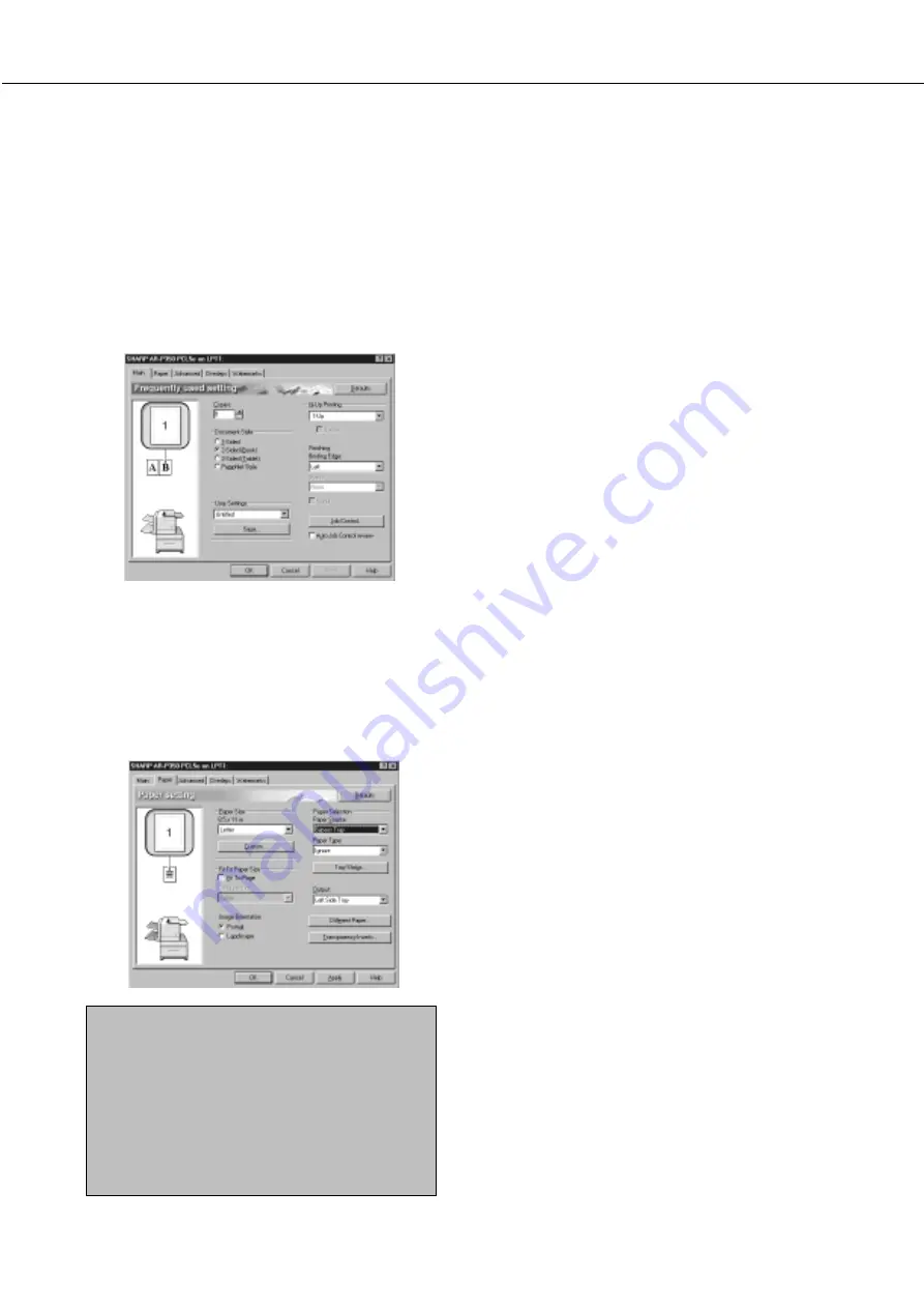
Two-sided printing
Open the “Main” tab and check the radio button of
the desired two-sided printing mode.
■
■
■
■
■
Using the bypass tray
Open the “Paper” tab shown in the illustration below
and select “Bypass Tray” in the “Paper Selection” drop
down.
■
■
■
■
■
Using the exit tray mounted to the duplex
module
Open the “Paper” tab shown in the illustration below
and select “Left Side Tray” in the “Output” drop down.
NOTES
●
The settings screens above will appear only if
the devices have been set properly in the printer
driver configuration (see NOTE on page 2-5).
●
The combination of paper selection and other
functions may not be compatible. For instance,
if heavy paper, envelopes, label stock, etc. are
selected, it will not be possible to select duplex,
offset tray, saddle stitch, etc. For details, see
printer driver help.
DUPLEX MODULE
Copying in the duplex mode
For copying in the duplex mode, press the COPY key
on the operation panel and make all selections on the
copy mode basic screen.
■
■
■
■
■
Automatic duplex copying
Touch the [2-SIDED COPY] key on the copy mode
basic screen. A selection screen for two-sided
copying will appear.
■
■
■
■
■
Using the bypass tray
Touch the [PAPER SELECT] key on the copy mode
basic screen. A selection screen for paper source
will appear. Select the bypass tray on this screen.
■
■
■
■
■
Using the exit tray
Touch the [OUTPUT] key on the copy mode basic
screen. A selection screen for output will appear.
Select the exit tray mounted to the duplex module
on this screen.
Summary of Contents for DM-3551
Page 2: ...cover1 p65 2 04 01 19 17 2 ...
Page 37: ...cover4 p65 2 04 01 19 18 1 ...
Page 40: ......
Page 69: ......
Page 90: ......
Page 98: ......
Page 120: ......
Page 126: ......
Page 159: ...9 3 9 NOTE ...
Page 160: ...9 4 NOTE ...
Page 161: ......
Page 178: ...1 6 Part names and functions of peripheral devices PART NAMES AND FUNCTIONS ...
Page 198: ...1 26 ...
Page 218: ...2 20 ...
Page 226: ......
Page 238: ......
Page 273: ......
Page 285: ......