
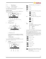
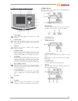


3a VRD Voltage Reduction Device
Shows that the no-load voltage of the equip-
ment is controlled.
3b Allows the selection of the welding process
MMA
TIG DC
TIG AC
3c Allows the selection of the welding method
Direct polarity
Reverse polarity
Alternating current
3d
Synergy
Allows you to set the best arc dynamics, select-
ing the type of electrode used:
STD
Basic/Rutile
CLS
Cellulose
CrNi
Steel
Alu
Aluminium
Cast iron Cast iron
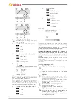
Selecting the correct arc dynamics enables maximum
benefit to be derived from the power source to achieve
the best possible welding performances.
Perfect weldability of the electrode used is not guaran-
teed (weldability depends on the quality of the consum-
ables and their preservation, the operating and welding
conditions, the numerous possible applications, etc.).
3e Allows the selection of the welding method
2 Step
4 Step
Bilevel
3f Current pulsation
CONSTANT current
PULSED current
Fast Pulse
3g
Current pulsation
CONSTANT current
PULSED current
AC/DC mix
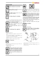
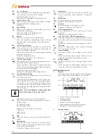
3.4 Set up
Permits set up and adjustment of a series of additional param-
eters for improved and more accurate control of the welding
system.
The parameters present at set up are organised in relation to the
welding process selected and have a numerical code.
Entry to set up:
by pressing the encoder key for 5 sec.
Selection and adjustment of the required parameter:
by
turning the encoder until displaying the numerical code relating
to that parameter. If the encoder key is pressed at this point,
the value set for the parameter selected can be displayed and
adjusted.
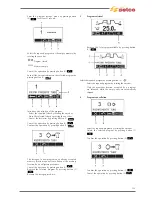
Exit from set up:
to quit the "adjustment" section, press the
encoder again.
To exit the set up, go to parameter "O" (save and quit) and press
the encoder.
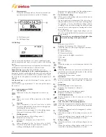
List of set up parameters (MMA)
0
Save and quit
Allows you to save the changes and exit the set up.
1
Reset
Allows you to reset all the parameters to the default
values.
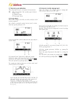
3 Hot
start
Allows adjustment of the hot start value in MMA.
Permits an adjustable hot start in the arc striking phases,
facilitating the start operations.
Parameter set as a percentage (%) of the welding current.
Minimum Off, Maximum 500%, Default 80%
7
Welding current
Permits adjustment of the welding current.
Parameter set in Amps (A).
Minimum 3A, Maximum Imax, Default 100A
8 Arc
force
Allows adjustment of the Arc force value in MMA.
Permits an adjustable energetic dynamic response in
welding, facilitating the welder's operations.
Increasing the value of the arc force to reduce the risks
of sticking of the electrode.
126
Summary of Contents for Genesis 1700 AC/DC
Page 1: ...Genesis 1700 AC DC Genesis 2200 AC DC MANUALE DI RIPARAZIONE REPAIR MANUAL ...
Page 51: ...161 PFC S POWER COMPONENTS D11 IG1 IG2 D1 D7 CN3 M1 CN4 CN5 CN8 CN7 M2 CN6 ...
Page 52: ...162 PFC STAGE LEDS INDICATIONS PFC s POWER COMPONENTS L2 L1 IG1 IG2 D1 CN6 D7 D11 ...
Page 54: ...164 INVERTER STAGE CN3 M1 CN4 CN5 CN8 CN7 M2 Inverter IMS power module ...
Page 62: ...172 15 Remove pcb T3 PFC s POWER COMPONENTS IG1 IG2 D1 NTC1 Unscrew torque screw at 2 2N mt ...
Page 64: ...174 DIODES AND PFC IGBT ORIENTATION Landmark for assembling ...
Page 67: ...177 12 4 Thermic caps inverter side NTC1 T3 CN11 ...
Page 69: ...179 12 5 Thermic caps secondary side T1 T2 15 14 434 CN3 CN2 ...
Page 74: ...184 15 14 439 15 14 42901 L3 L4 L1 L2 ...
Page 75: ...185 Gas valve flow chart signal Pipe 38 39 ...
Page 79: ...189 CN6 15 14 415 CN3 15 14 431 FLAT A FLAT B Inverter commands Boost commands ...
Page 80: ...190 By pass relais flow chart Gas valve ELVI Fan M1 and M2 command signal ...
Page 81: ...191 HF command signal AC command signal Torch switch buttons signals ...
Page 88: ...198 HF pulse in TIG AC HF pulse in TIG DC ...
Page 114: ...224 GENESIS 2200 AC DC FP279 ...
Page 115: ...225 GENESIS 1700 AC DC FP216 ...
Page 116: ...226 GENESIS 2200 AC DC FP216 ...
Page 118: ...228 20 CONNETTORI CONNECTORS GENESIS 1700 AC DC FP279 GENESIS 2200 AC DC FP279 ...
Page 119: ...229 GENESIS 1700 AC DC FP216 GENESIS 2200 AC DC FP216 ...
Page 122: ...232 55 08 022 55 08 023 GENESIS 1700 AC DC FP216 GENESIS 2200 AC DC FP216 ...