


9) INSTRUMENTS AND CONVENTIONS FOR
PERFORMING DIAGNOSIS AND REPAIR
9.1) Instruments for basic diagnosis
The following are required:
- a multimeter with the following scales:
Ohm: from 0 ohm to a few Mohm
Diode
testing
Direct voltage (Vdc): from mVdc to 1000 Vdc
Alternating voltage (Vac): from 10 Vac to 700Vac
NOTE:
You are advised to use an instrument with automatic
scale since it is not theoretically possible to predict the electrical
quantity to be measured when the machine has broken down.
SEVERAL MEASURAMENT SHOULD BE PLACED ON
CONNECTORS SIDE. PAY PARTICULAR ATTENTION IN
ORDER TO AVOID ANY ACCIDENTAL SHORT CIRCUIT
BETWEEN CONNECTOR'S PIN OR TEST LEADS. THE USE
OF THIN CONDUCTORS AS RESISTANCE LEADS COULD BE
HELPFULL ON MEASURAMENT STAGE.
- an AC/DC ammeter clamp at least in class 2.5 with e.o.s.
300A pk.
9.2) Repair tools
- Complete set of fork spanners
- Complete set of pipe spanners for hexagonal nuts
- Complete set of blade screwdrivers
- Complete set of Phillips screwdrivers
- Complete set of Allen keys
- Dynamometric screws driver for fix M3 with adjustable
torque range 1÷3Nxm tolerance 0.1Nxm
- Crimper for insulated wire terminals (blue, red and yellow)
- Pliers for AMP contacts
- Tweezers and cutting nippers - type commonly used for elec-
tronic components
- Tongs (dimensions suitable for closing gas pipe clamps)
- Welder for electronic components, minimum power 50 W
- Portable electric drill
9.3) Conventions
By convention, when a measurement has to be taken between
two points, for example a
b, the arrow point indicates
where to apply the red tip of the multimeter (a),while the black
tip is applied at the other end (b).
When a double arrow appears between two measuring points
(e.g.: c
d), the voltage to be measured is alternating (nor-
mally at 50Hz or 60Hz), therefore it does not matter in which
order the multimeter terminals are applied.
In drawings and tables, when a voltage measurement appears
referring to terminals of components such as DIODES, BJT,
MOSFET and IGBT, the multimeter is used in "diode test"
mode (these measurements are always taken with the machine
switched off and normally give values in the range +0.10 …
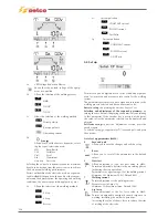
+0.90Vdc). In this case the following symbol is affixed beside
the value to be measured:
Junction measurement (multimeter in "diode test"
mode)
The following symbols will be used in the same way:
AC or DC voltage measurement (multimeter in
voltmeter
mode)
Resistance measurement (multimeter in ohmmeter
mode)
Current measurement (ammeter clamp or shunt +
multimeter in millivoltmeter mode)
Frequency measurement (multimeter in frequen-
cymeter mode)
The measuring conditions (power source on/off, MMA/TIG
operating mode, etc.) are always clearly indicated beside the
values to be measured.
The connector terminals are indicated by the name of the con-
nector followed by a slash and the number of the terminal; for
example CN1/2 indicates terminal 2 of connector CN1.
Unless otherwise specified, all the measurements must be per-
formed with the boards fitted, together with their connections.
Remember that the first of the tests to be per-
formed is the VISUAL CHECK!
The visual check reduces troubleshooting times and directs
any subsequent tests towards the damaged part!
140
Summary of Contents for Genesis 1700 AC/DC
Page 1: ...Genesis 1700 AC DC Genesis 2200 AC DC MANUALE DI RIPARAZIONE REPAIR MANUAL ...
Page 51: ...161 PFC S POWER COMPONENTS D11 IG1 IG2 D1 D7 CN3 M1 CN4 CN5 CN8 CN7 M2 CN6 ...
Page 52: ...162 PFC STAGE LEDS INDICATIONS PFC s POWER COMPONENTS L2 L1 IG1 IG2 D1 CN6 D7 D11 ...
Page 54: ...164 INVERTER STAGE CN3 M1 CN4 CN5 CN8 CN7 M2 Inverter IMS power module ...
Page 62: ...172 15 Remove pcb T3 PFC s POWER COMPONENTS IG1 IG2 D1 NTC1 Unscrew torque screw at 2 2N mt ...
Page 64: ...174 DIODES AND PFC IGBT ORIENTATION Landmark for assembling ...
Page 67: ...177 12 4 Thermic caps inverter side NTC1 T3 CN11 ...
Page 69: ...179 12 5 Thermic caps secondary side T1 T2 15 14 434 CN3 CN2 ...
Page 74: ...184 15 14 439 15 14 42901 L3 L4 L1 L2 ...
Page 75: ...185 Gas valve flow chart signal Pipe 38 39 ...
Page 79: ...189 CN6 15 14 415 CN3 15 14 431 FLAT A FLAT B Inverter commands Boost commands ...
Page 80: ...190 By pass relais flow chart Gas valve ELVI Fan M1 and M2 command signal ...
Page 81: ...191 HF command signal AC command signal Torch switch buttons signals ...
Page 88: ...198 HF pulse in TIG AC HF pulse in TIG DC ...
Page 114: ...224 GENESIS 2200 AC DC FP279 ...
Page 115: ...225 GENESIS 1700 AC DC FP216 ...
Page 116: ...226 GENESIS 2200 AC DC FP216 ...
Page 118: ...228 20 CONNETTORI CONNECTORS GENESIS 1700 AC DC FP279 GENESIS 2200 AC DC FP279 ...
Page 119: ...229 GENESIS 1700 AC DC FP216 GENESIS 2200 AC DC FP216 ...
Page 122: ...232 55 08 022 55 08 023 GENESIS 1700 AC DC FP216 GENESIS 2200 AC DC FP216 ...