


220
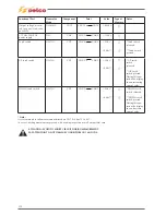
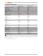
16) TECHNICAL SPECIFICATIONS
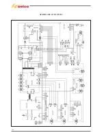
GENESIS 1700 AC/DC
GENESIS 2200 AC/DC
Power supply voltage U1 (50/60Hz)
1x230V/115V ±15%
1x230V/115V ±15%
Zmax (@PCC)
*
349m
Ω
275m
Ω
Slow blow line fuse
16A/25A
20A/30A
Communication bus
DIGITAL
DIGITAL
Maximum input power (kVA)
5 kVA
6.4 kVA
Maximum input power (kW)
5 kW
6.4 kW
Power factor PF
1
1
Efficiency (
μ
) 80%
80%
Cos
ϕ
0.99
0.99
Max. input current I1max
21.7A/33.3A
27.6A/37.2A
Effective current I1eff
12.5A/19.5A
16A/22A
MMA duty factor (40°C)
(x=35%)
150/120A
180/130A
(x=60%)
120/100A
150/110A
(x=100%)
90/80A
130/90A
MMA duty factor (25°C)
(x=60%)
-
180A
(x=100%)
150/120A
160/130A
TIG duty factor (40°C)
(x=35%)
170/150A
220/180A
(x=60%)
150/130A
170/140A
(x=100%)
130/110A
150/130A
TIG duty factor (25°C)
(x=60%)
-
220A
(x=100%)
170/150A
180/180A
Adjustment range I2
MMA
3-150A
3-180A
TIG
3-170A
3-220A
Open circuit voltage Uo
80V
80V
Peak voltage Up
10.1kV
10.1kV
IP Protection rating
IP23S
IP23S
Insulation class
H
H
Dimensions (lxdxh)
500x190x400 mm
500x190x400 mm
Weight
18.8 Kg.
18.8 Kg.
Manufacturing Standards
EN 60974-1/EN 60974-3
EN 60974-1/EN 60974-3
EN 60974-10
EN 60974-10
Power supply cable
3x2.5 mm2
3x2.5 mm2
Length of power supply cable
5m
5m
*
This equipment complies with EN/IEC 61000-3-11 if the maximum permissible mains impedance at the interface point to the public grid
(point of common coupling, PCC) is smaller than or equal to the Zmax stated value. If it is connected to a public low voltage system, it is the
responsibility of the installer or user of the equipment to ensure, by consultation with the distribution network operator if necessary, that the
equipment may be connected.
*
This equipment complies with EN/IEC 61000-3-12.
Summary of Contents for Genesis 1700 AC/DC
Page 1: ...Genesis 1700 AC DC Genesis 2200 AC DC MANUALE DI RIPARAZIONE REPAIR MANUAL ...
Page 51: ...161 PFC S POWER COMPONENTS D11 IG1 IG2 D1 D7 CN3 M1 CN4 CN5 CN8 CN7 M2 CN6 ...
Page 52: ...162 PFC STAGE LEDS INDICATIONS PFC s POWER COMPONENTS L2 L1 IG1 IG2 D1 CN6 D7 D11 ...
Page 54: ...164 INVERTER STAGE CN3 M1 CN4 CN5 CN8 CN7 M2 Inverter IMS power module ...
Page 62: ...172 15 Remove pcb T3 PFC s POWER COMPONENTS IG1 IG2 D1 NTC1 Unscrew torque screw at 2 2N mt ...
Page 64: ...174 DIODES AND PFC IGBT ORIENTATION Landmark for assembling ...
Page 67: ...177 12 4 Thermic caps inverter side NTC1 T3 CN11 ...
Page 69: ...179 12 5 Thermic caps secondary side T1 T2 15 14 434 CN3 CN2 ...
Page 74: ...184 15 14 439 15 14 42901 L3 L4 L1 L2 ...
Page 75: ...185 Gas valve flow chart signal Pipe 38 39 ...
Page 79: ...189 CN6 15 14 415 CN3 15 14 431 FLAT A FLAT B Inverter commands Boost commands ...
Page 80: ...190 By pass relais flow chart Gas valve ELVI Fan M1 and M2 command signal ...
Page 81: ...191 HF command signal AC command signal Torch switch buttons signals ...
Page 88: ...198 HF pulse in TIG AC HF pulse in TIG DC ...
Page 114: ...224 GENESIS 2200 AC DC FP279 ...
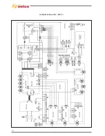
Page 115: ...225 GENESIS 1700 AC DC FP216 ...
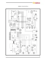
Page 116: ...226 GENESIS 2200 AC DC FP216 ...
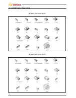
Page 118: ...228 20 CONNETTORI CONNECTORS GENESIS 1700 AC DC FP279 GENESIS 2200 AC DC FP279 ...
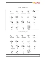
Page 119: ...229 GENESIS 1700 AC DC FP216 GENESIS 2200 AC DC FP216 ...
Page 122: ...232 55 08 022 55 08 023 GENESIS 1700 AC DC FP216 GENESIS 2200 AC DC FP216 ...


