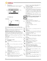
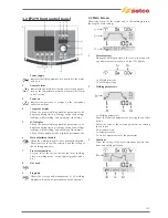


3.12 Rear panel
1
Power supply cable
Connects the system to the mains.
2 Gas
fitting
3
Signal cable (CAN-BUS) input (RC)
4 Off/On
switch
Turns on the electric power to the welder.
It has two positions, "O" off, and "I" on.
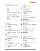
3.13 Sockets panel
1
Negative power socket
For connection of earth cable in electrode welding or of
torch in TIG.
2
Positive power socket
For connection of electrode torch in MMA or earth
cable in TIG.
3 Gas
fitting
4
Signal cable (TIG Torch) input
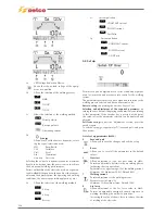
4 ACCESSORIES
4.1 General
Operation of the remote control is activated when connected
to the Selco power sources. This connection can be made also
with the system power on.
With the RC control connected, the power source control panel
stays enabled to perform any modification. The modifications
on the power source control panel are also shown on the RC
control and vice versa.
4.2 RC 100 remote control
The RC 100 is a remote control unit designed to manage the
display and the adjustment of the welding current and voltage.
“Consult the instruction manual”.
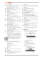
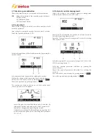
4.3 RC 120 pedal remote control unit for TIG
welding
Once the power source has been switched
to the EXTERNAL CONTROL mode, the
output current is controlled from a mini-
mum to a maximum value (can be entered
from SETUP) by varying the foot pressure on
the pedal surface. A microswitch provides
the start trigger signal at minimum pressure.
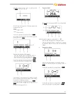
4.4 RC 180 remote control
This remote control unit makes it possible to change the output
current without interrupting the welding process.
“Consult the instruction manual”.
134
Summary of Contents for Genesis 1700 AC/DC
Page 1: ...Genesis 1700 AC DC Genesis 2200 AC DC MANUALE DI RIPARAZIONE REPAIR MANUAL ...
Page 51: ...161 PFC S POWER COMPONENTS D11 IG1 IG2 D1 D7 CN3 M1 CN4 CN5 CN8 CN7 M2 CN6 ...
Page 52: ...162 PFC STAGE LEDS INDICATIONS PFC s POWER COMPONENTS L2 L1 IG1 IG2 D1 CN6 D7 D11 ...
Page 54: ...164 INVERTER STAGE CN3 M1 CN4 CN5 CN8 CN7 M2 Inverter IMS power module ...
Page 62: ...172 15 Remove pcb T3 PFC s POWER COMPONENTS IG1 IG2 D1 NTC1 Unscrew torque screw at 2 2N mt ...
Page 64: ...174 DIODES AND PFC IGBT ORIENTATION Landmark for assembling ...
Page 67: ...177 12 4 Thermic caps inverter side NTC1 T3 CN11 ...
Page 69: ...179 12 5 Thermic caps secondary side T1 T2 15 14 434 CN3 CN2 ...
Page 74: ...184 15 14 439 15 14 42901 L3 L4 L1 L2 ...
Page 75: ...185 Gas valve flow chart signal Pipe 38 39 ...
Page 79: ...189 CN6 15 14 415 CN3 15 14 431 FLAT A FLAT B Inverter commands Boost commands ...
Page 80: ...190 By pass relais flow chart Gas valve ELVI Fan M1 and M2 command signal ...
Page 81: ...191 HF command signal AC command signal Torch switch buttons signals ...
Page 88: ...198 HF pulse in TIG AC HF pulse in TIG DC ...
Page 114: ...224 GENESIS 2200 AC DC FP279 ...
Page 115: ...225 GENESIS 1700 AC DC FP216 ...
Page 116: ...226 GENESIS 2200 AC DC FP216 ...
Page 118: ...228 20 CONNETTORI CONNECTORS GENESIS 1700 AC DC FP279 GENESIS 2200 AC DC FP279 ...
Page 119: ...229 GENESIS 1700 AC DC FP216 GENESIS 2200 AC DC FP216 ...
Page 122: ...232 55 08 022 55 08 023 GENESIS 1700 AC DC FP216 GENESIS 2200 AC DC FP216 ...